English
 Español
Customized Circular Vertical Lifting Rack Electroplating Line
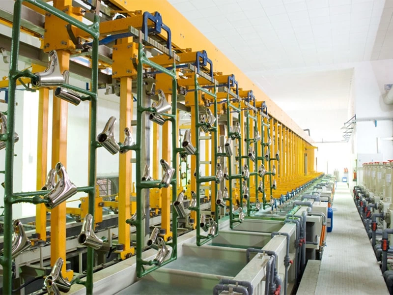
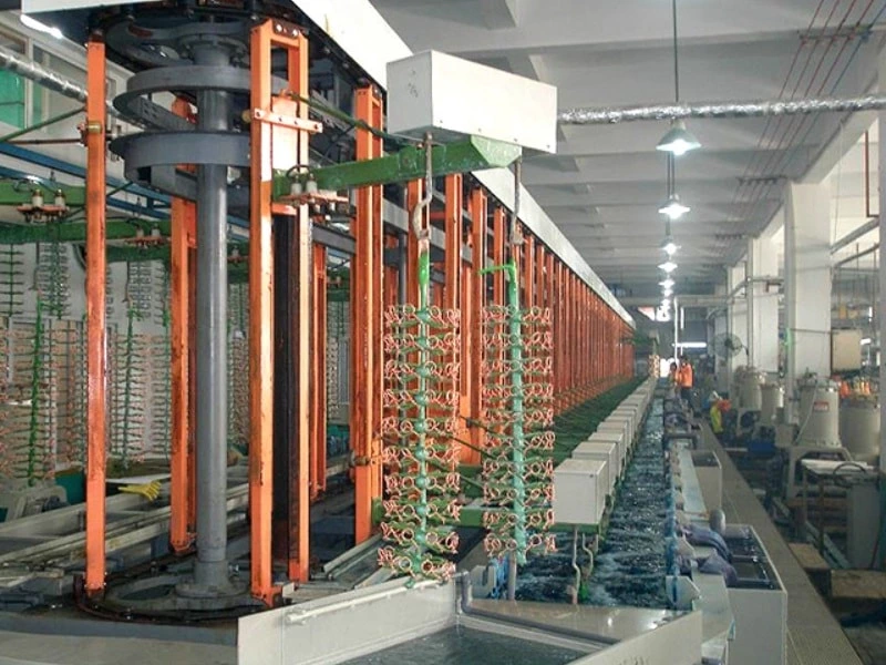
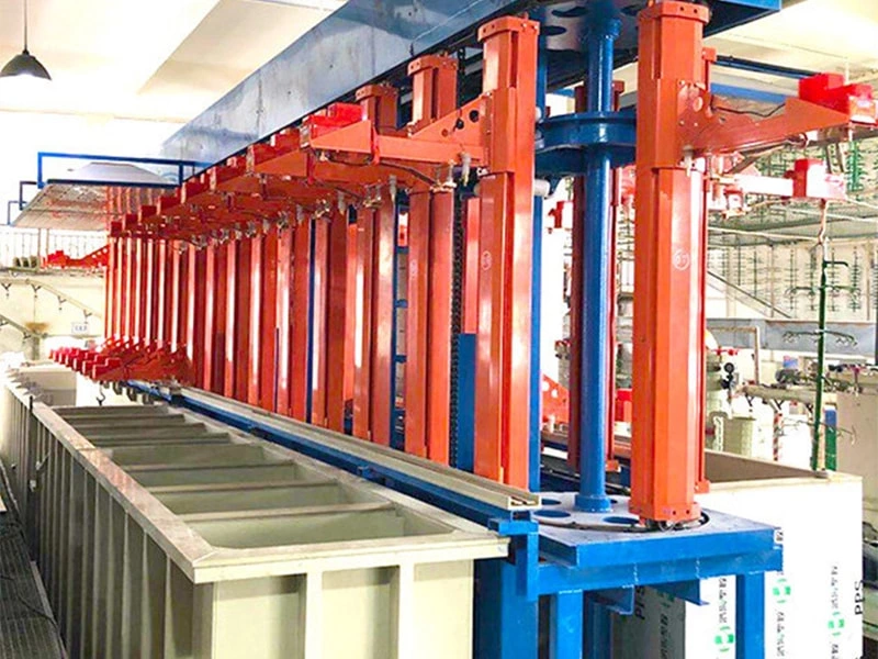
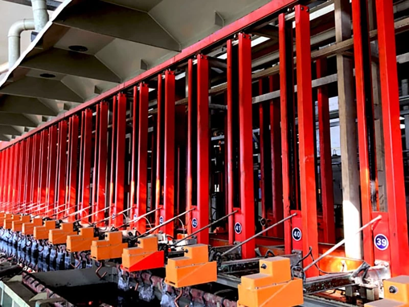
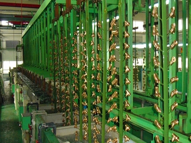
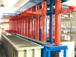
This customized circular vertical lifting rack electroplating line is engineered for repeat production where loaded racks follow a defined process sequence around a closed-loop transfer path. Rack size, tank geometry, lifting capacity, current delivery, cycle time, controls and auxiliary systems are configured from the actual workpieces, coating specification, production target and workshop conditions.
- Feature
- Closed-loop rack transfer with vertical lifting
- Materials
- Selected according to the approved plating chemistry
- Application
- Rack plating of large or long repeat-production parts
- Speed
- Engineered from the required process time and production target
- Max Plated Parts
- Confirmed from the loaded rack envelope and transfer capacity
- Auxiliary Equipment
- Rectifiers, filters, temperature control, exhaust and PLC/HMI as required
PRODUCT SUMMARY
A circular vertical lifting rack electroplating line is a project-engineered production system in which loaded racks move through a defined sequence of process and rinse tanks along a closed-loop route. It is intended for repeat production where part orientation, electrical contact, immersion time and transfer order must remain controlled from one load to the next.
This configuration can be considered when larger or longer rack loads, a stable process sequence and the available workshop layout make a circular transfer arrangement practical. It is not a standard machine selected only by the length of a workpiece. Tank dimensions, rack spacing, lifting capacity, current delivery, cycle time and auxiliary equipment must be calculated from the actual parts and coating requirements.
AutoPlatingTec configures the line around the buyer's approved process, production target, loaded rack envelope and factory conditions. The final scope may include process tanks, rinse stages, rack transfer equipment, rectifiers, busbars, filtration, heating or cooling, PLC/HMI controls, platforms, guarding, exhaust interfaces and other project-specific equipment.
PRODUCT DETAILS
How the Circular Vertical Lifting Arrangement Works
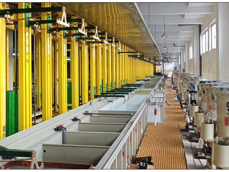
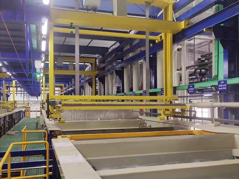
In a circular or annular layout, racks follow a repeating transfer route instead of moving back and forth along a single straight gantry path. At each programmed step, a rack is lifted clear of one tank, transferred to the next assigned position and lowered according to the approved process sequence. Loading and unloading positions are incorporated into the route so that production can continue in a controlled cycle.
The exact transfer mechanism is selected during engineering. Depending on the project, the system may use lifting stations, indexing transfer devices, mechanical rack-handling interfaces or other arrangements suited to the rack load and line geometry. Vertical clearance, sway control, drip containment, collision zones, emergency recovery and maintenance access must be reviewed together rather than treated as separate details.
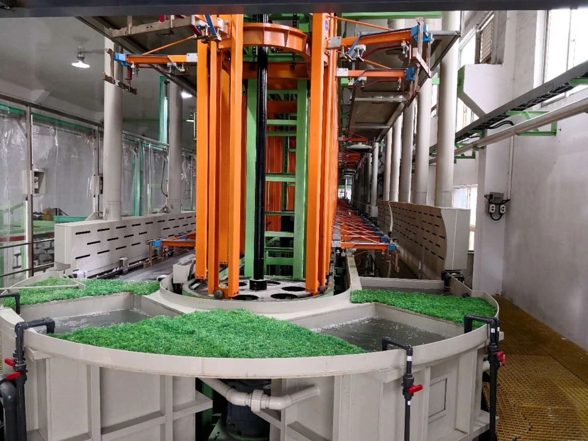
A closed-loop arrangement does not automatically guarantee a higher output or a smaller footprint. Its suitability depends on process dwell times, the number of available positions, loading frequency, part mix and factory layout. Capacity must therefore be calculated from the complete operating cycle.
When This Line Configuration Is a Good Fit
A customized circular vertical lifting line is most suitable when the following conditions are present:
- The workpieces can be held securely on plating racks with repeatable orientation and electrical contact.
- The production program uses a stable process sequence with predictable immersion and transfer times.
- The loaded rack envelope, tank length or transfer arrangement requires a project-specific mechanical design.
- Production demand is high enough to justify dedicated automatic handling and process control.
- The workshop can accommodate the full line, loading area, maintenance access, platforms, utilities, exhaust and wastewater interfaces.
It may not be the best choice for prototype work, very small and frequently changing batches, parts that cannot be held reliably on racks, or production that requires major route changes from one load to the next. In these cases, a different rack electroplating line layout or a more flexible handling concept may be more appropriate.
Circular Vertical Lifting Line vs. Linear Gantry Rack Line
Both arrangements can be automated, but they organize movement and production differently. The choice should be based on process logic and factory constraints rather than on a general claim that one design is always better.
| Evaluation Point | Circular Vertical Lifting Arrangement | Linear Gantry Arrangement |
|---|---|---|
| Transfer route | Racks follow a repeating closed-loop sequence. | Hoists normally travel along one or more straight tank rows. |
| Production pattern | Well suited to repeat production with a stable route and loading rhythm. | Can provide greater routing flexibility when recipes or dwell times vary. |
| Layout planning | Requires coordinated planning of the loop, loading positions and access around the line. | Requires sufficient line length, crane travel clearance and service access beside the tank rows. |
| Capacity calculation | Depends on the slowest process step, number of positions and indexing cycle. | Depends on hoist quantity, scheduling logic, dwell times and transfer conflicts. |
| Best selection basis | Part data, approved process, loading method, production demand, utilities, maintenance strategy and available space. | |
For a broader project-planning checklist, see How to Plan an Automatic Rack Electroplating Line.
Engineering the Line Around the Loaded Rack
The engineering reference is the complete loaded rack, not an isolated maximum part dimension. The supplier needs the workpiece drawings or representative samples, material, quantity per rack, total loaded weight, plated surface area, critical surfaces, drainage orientation and allowable contact marks. Rack drawings and contact details are also required when the buyer already has an established racking method.
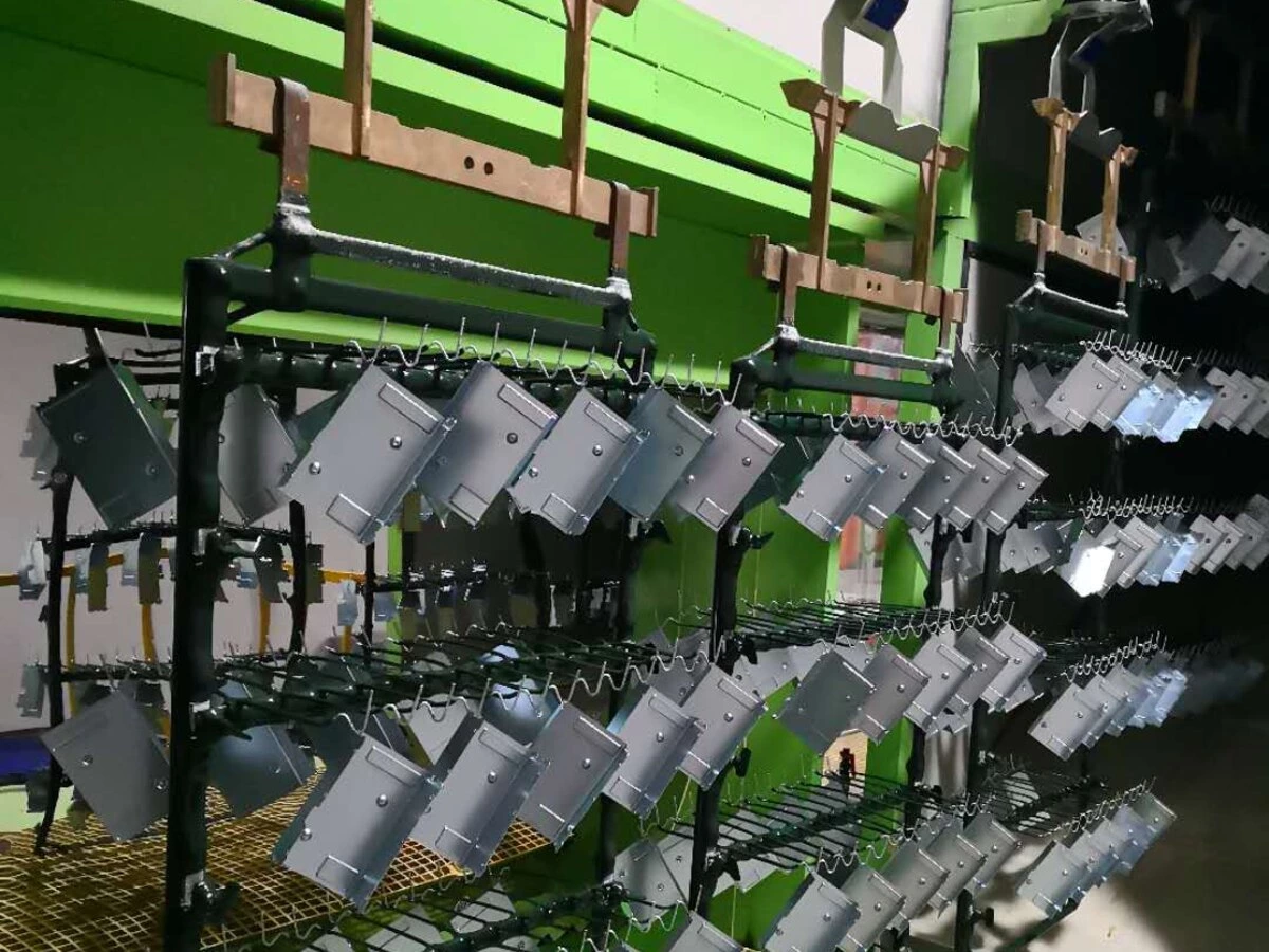
These data determine tank working dimensions, spacing between loads, lift stroke, transfer clearances, structure loads and current-carrying components. They also affect solution drag-out, rinse demand, rack stripping requirements and the time allowed for loading and unloading.
Long or uneven loads require particular attention to balance and movement. The design must prevent contact with tank walls, anodes, heating coils, pipework and adjacent racks throughout lifting and transfer. A stated workpiece length alone cannot confirm whether a part is suitable for the line.
Process Tanks and Bath Support Equipment
The process sequence is established from the substrate, surface condition, required coating system and post-treatment specification. A line may include cleaning, activation, plating, recovery, rinsing, passivation, sealing or other stages, but the actual route must be approved for the intended chemistry and product standard.
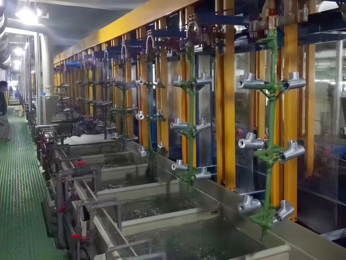
Tank material and construction are selected for the solution chemistry, temperature, load, dimensions and service life. Large or long tanks may require structural reinforcement and deflection control. Freeboard, overflow arrangement, drainage, leak containment, access and maintenance space must be considered together with the tank dimensions.
Bath-support equipment may include pumps, filters, eductors, agitation, heating, cooling, level control, dosing interfaces, anode systems and solution-transfer connections. Each item is selected from process demand rather than added as a generic accessory. If continuous filtration is required, flow rate, media, seal materials, solids loading and maintenance access must be confirmed.
Current Delivery and Rectifier Integration
Rectifier capacity is calculated from the maximum plated surface area per load, specified current-density range, contact efficiency and operating margin. It should not be selected from a single unverified amperage stated on a standard product page.
The complete current path includes the rectifier, cables or busbars, rack contacts, cathode bars and workpiece contact points. Contact pressure, heat generation, voltage drop, corrosion exposure and cleaning access all affect operating stability. Where current ramping, recipe control or ampere-hour monitoring is required, these functions must be defined during the control review.
Rectifier location, cooling method, enclosure rating and communication with the PLC are coordinated with the workshop environment and electrical standard. The final design must also include the required interlocks so that current cannot be applied under unsafe or incorrect process conditions.
Controls, Interlocks and Production Recovery
A PLC and HMI can coordinate transfer steps, process dwell times, tank availability, rectifier commands, temperature status and production alarms. Recipe access, user permissions, data records and communication interfaces are configured according to the project scope; they are not assumed to be identical for every line.
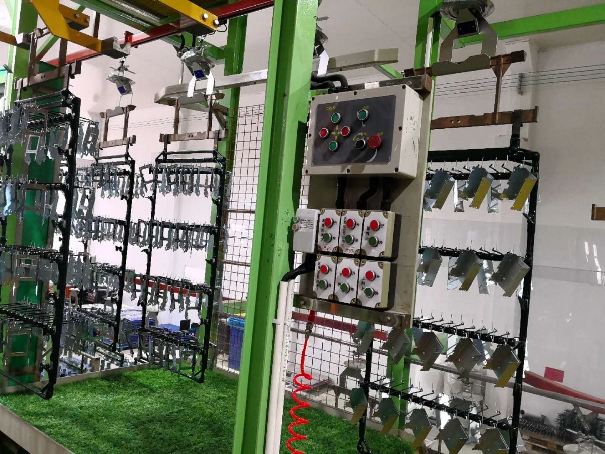
Automation must also address abnormal conditions. The control plan should define what happens after an obstruction, sensor fault, drive alarm, emergency stop or power interruption. Operators need a controlled manual-recovery method that identifies rack position and prevents an incorrect next step when production resumes.
Safety functions may include guarding, access interlocks, emergency stops, overload protection, anti-collision logic and alarms. The exact safety design and conformity requirements must be confirmed for the installation country and the customer's factory standards.
Rinsing, Drag-Out and Wastewater Interfaces
Rinsing is part of the process design, not an afterthought. Rack orientation, drain time, transfer path and solution viscosity affect drag-out from one stage to the next. Rinse stages may use single, counterflow, spray or other arrangements according to contamination limits, water availability and wastewater strategy.
The line supplier needs the buyer's water-quality requirements, available pressure and flow, discharge limits and wastewater-treatment boundary. Recovery rinses, conductivity control or flow regulation can be evaluated when they are compatible with the chemistry and production conditions.
See the Electroplating Rinse System Design Guide for the relationship between drag-out, rinse arrangement and water consumption.
Exhaust, Enclosure and Workshop Interfaces
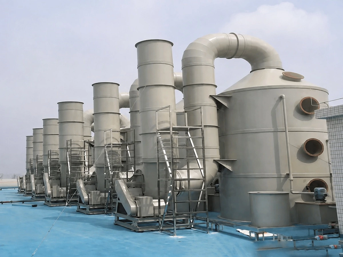
Process tanks that release acid mist, alkaline mist, vapor or other contaminants require an exhaust concept based on the actual bath and local requirements. Tank covers, side-slot hoods, partial enclosures or line enclosures may be considered, but capture design must allow for rack movement, loading, inspection and maintenance.
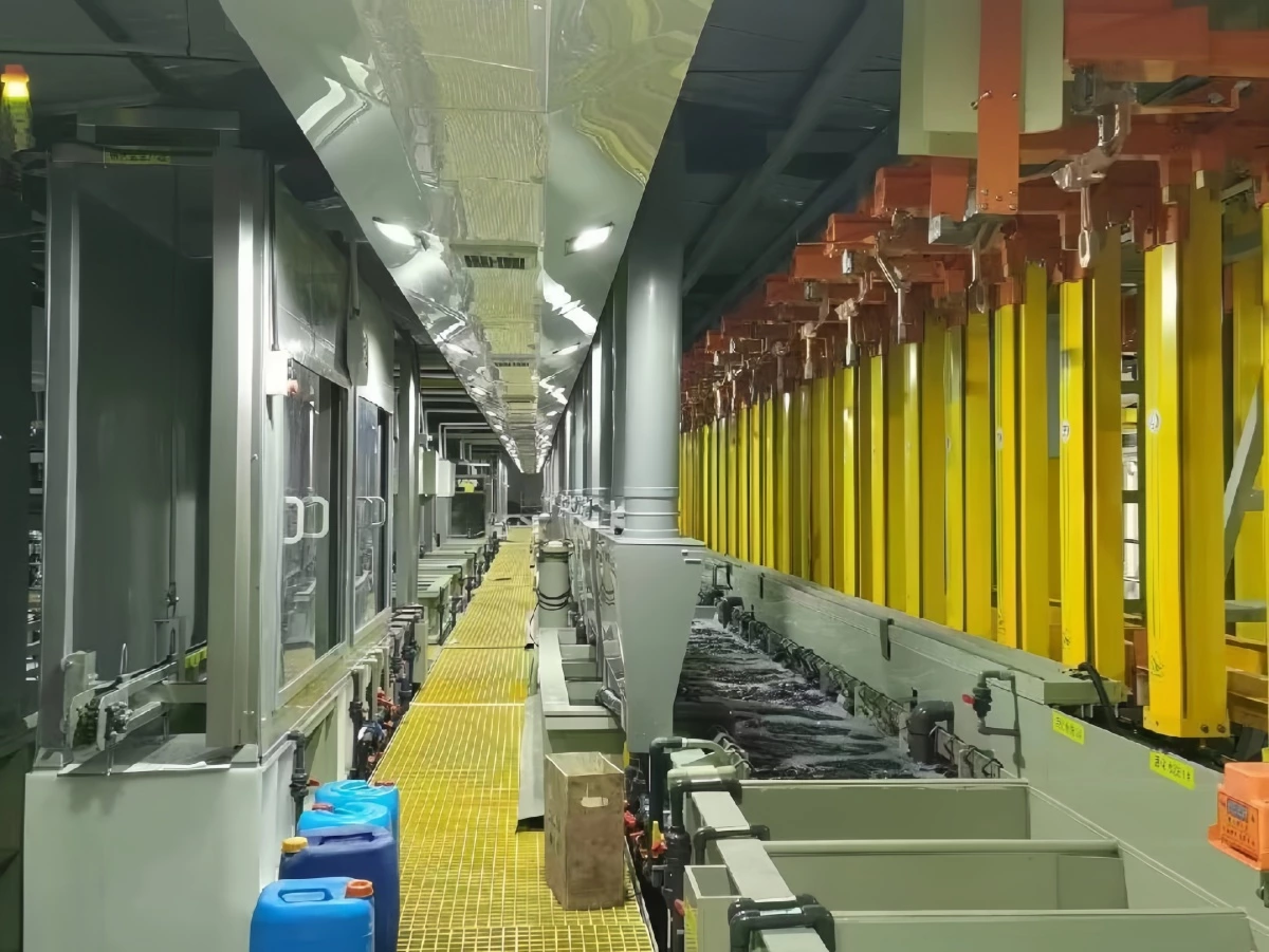
Exhaust airflow, duct material, fan duty and treatment method cannot be finalized without the tank openings, chemistry, temperature, hood arrangement, duct route and applicable emission limits. The equipment supplier and customer should agree whether the project includes collection hoods and ducts only or a complete electroplating exhaust gas treatment system.
The layout must also reserve safe access to filters, pumps, valves, rectifiers, electrical cabinets and lifting components. Floor load, pit or bund arrangement, drainage, ceiling height, incoming utilities and the route for equipment installation must be checked before the design is released.
Typical Supply Scope
Depending on the confirmed project boundary, the electroplating line supply may include:
- Steel structure and circular vertical lifting rack-transfer equipment
- Process, recovery and rinse tanks
- Loading, unloading and rack-handling interfaces
- Rectifiers, busbars and cathode contact systems
- Pumps, filters, pipework and temperature-control equipment
- PLC, HMI, sensors, alarms and electrical control cabinets
- Platforms, access stairs, guarding and drip-management provisions
- Tank hoods, exhaust collection interfaces or a project-specific treatment system
- Documentation, factory testing, installation guidance and commissioning support as agreed
The quotation should identify inclusions, exclusions and interface points. Civil works, incoming electrical supply, process chemicals, laboratory equipment, wastewater treatment, exhaust discharge stacks, permits and local installation labor must not be assumed unless they are specifically included.
Information Required for Design and Quotation
To evaluate the line and prepare a meaningful proposal, please provide:
- Part drawings, photographs, material and surface condition
- Maximum and minimum part dimensions and weight
- Parts per rack, loaded rack dimensions, total load weight and rack drawings
- Total plated surface area per rack and required current-density range
- Coating system, thickness, appearance and applicable acceptance standard
- Approved pretreatment, plating, rinse and post-treatment sequence
- Required output by hour, shift, day or year, including production mix
- Available workshop layout, ceiling height, access route and maintenance clearances
- Electrical supply, water quality, compressed air, heating and cooling utilities
- Exhaust, wastewater, safety, traceability and local compliance requirements
- Required automation, production-data and factory-system interfaces
- Expected supply boundary, FAT, installation, training and commissioning scope
If some information is not yet available, identify it as pending instead of replacing it with an assumed value. This allows the proposal to separate confirmed design inputs from provisional allowances.
Factory Acceptance Test, Installation and Commissioning
Before shipment, the factory acceptance test should verify the functions that can be demonstrated at the supplier's facility. Depending on the agreed scope, this may include structure and tank inspection, dry-cycle transfer tests, sensor and interlock checks, PLC/HMI operation, alarm simulation, documentation review and confirmation of purchased components.
Process performance with production chemistry and actual parts may require site conditions and should not be represented as completed during a dry FAT unless the test method explicitly includes those conditions. Acceptance responsibilities, test loads, utilities, records and corrective-action procedures should be agreed before testing.
For more detail, read Factory Acceptance Test (FAT) for Electroplating Lines. Workshop preparation should also be completed against the Electroplating Line Site Preparation Checklist before equipment arrives.
FREQUENTLY ASKED QUESTIONS
What is the main difference between a circular vertical lifting line and a linear gantry line?
A circular line moves racks through a repeating closed-loop sequence, while a linear gantry line normally uses one or more hoists travelling along straight tank rows. The correct choice depends on process timing, route flexibility, loaded rack data, production mix, space and maintenance access.
Can the line process different part models?
It can process compatible part families when their racks, electrical demand, process route, dwell times and clearances fall within the approved design range. A new part should be reviewed before it is added to production; recipe changes alone cannot correct an incompatible rack load or process route.
How is production capacity calculated?
Capacity is calculated from parts per rack, loading frequency, process dwell times, transfer time, number of available positions, bottleneck stages, planned utilization and product mix. A reliable output figure cannot be calculated from line speed or part length alone.
Which plating processes can be used?
The mechanical layout can be engineered for selected rack-plating processes, but tank materials, ventilation, filtration, heating or cooling, anodes, rectifiers and controls must match the approved chemistry. The coating system and chemical supplier's requirements should be confirmed before detailed design.
Can exhaust and wastewater equipment be included?
Collection hoods, ducts, exhaust treatment interfaces and wastewater connections can be included according to the agreed project boundary. A complete treatment system requires confirmed airflow or wastewater data, contaminant characteristics, discharge requirements and local compliance criteria.
What should be confirmed before requesting a quotation?
At minimum, provide representative part data, loaded rack information, coating specification, process sequence, production target, workshop layout, utilities and the expected supply boundary. The more complete these inputs are, the more accurately the supplier can define equipment, interfaces, price and lead time.
REQUEST A PROJECT EVALUATION
Send AutoPlatingTec your part drawings or photographs, loaded rack data, coating requirement, production target and available workshop layout. Our engineering team will review whether a circular vertical lifting rack line is suitable and identify the information still required for a technical proposal.
Request a Quote
If you are interested in our products and want to know more details,please leave a message here,we will reply you as soon as we can.