English
 Español
Electroplating Rack Design and Plating Yield
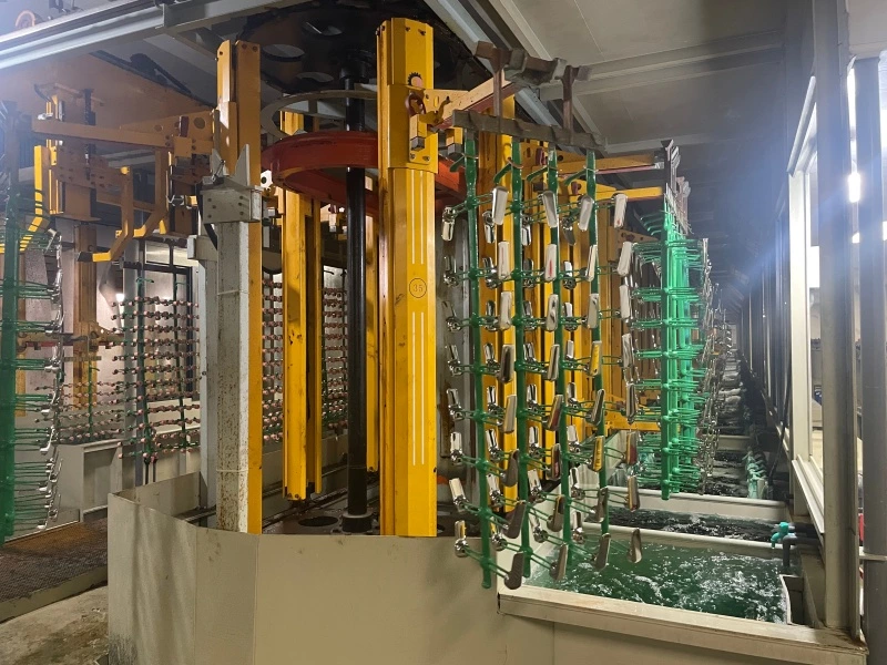
In rack electroplating, coating problems are not always caused by bath chemistry or rectifier settings. In many production cases, uneven coating thickness, edge burning, poor coverage in holes, and unstable corrosion resistance are related to one overlooked factor: the electroplating rack design.
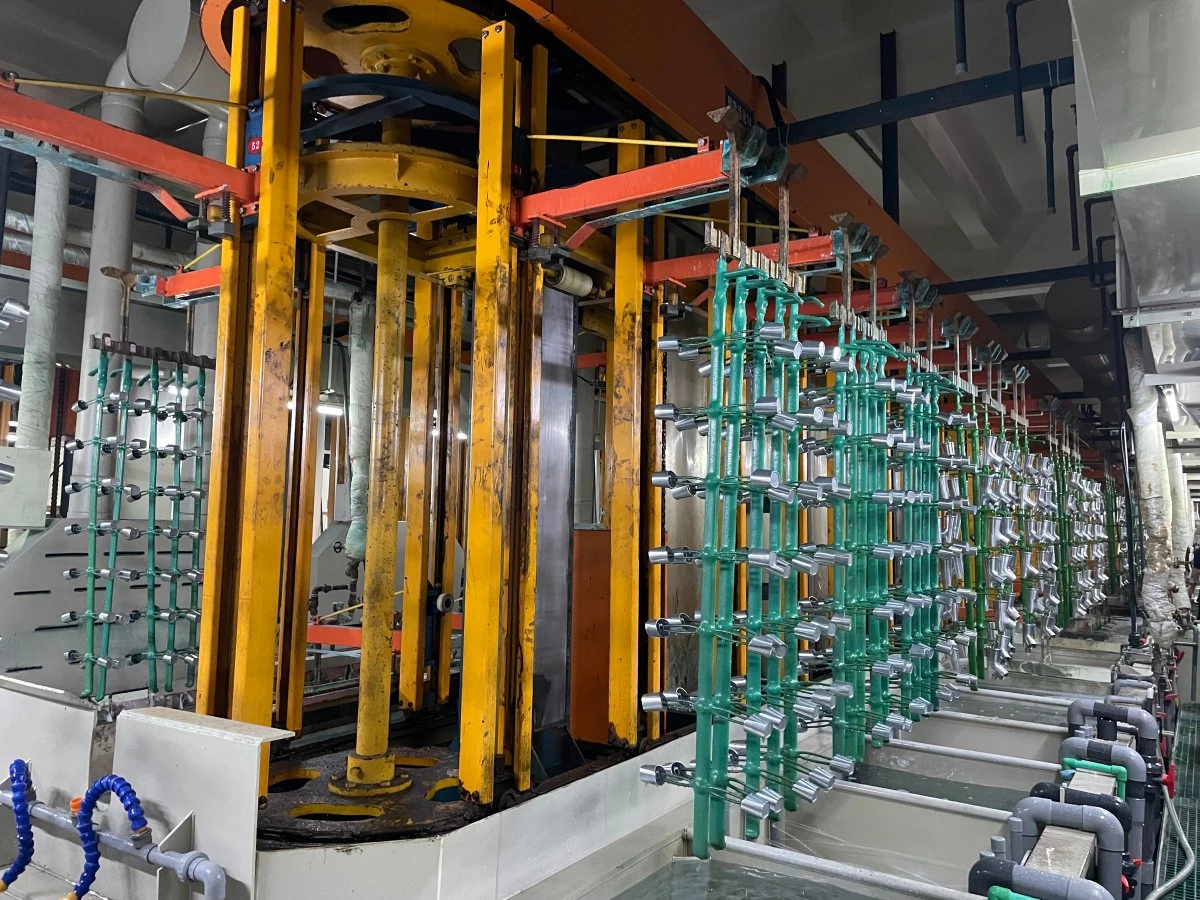
A plating rack is not only used to hold parts. It also affects electrical contact, current distribution, solution flow, gas release, liquid drainage, and loading stability. For automatic rack plating lines, these details can directly influence plating quality, rework rate, and final production cost.
For manufacturers of automotive parts, hardware components, bathroom fittings, electronics, mechanical parts, and decorative metal products, rack design should be treated as an important part of the plating process, not just as a simple fixture.
What Does an Electroplating Rack Do?
The basic function of an electroplating rack is to hold workpieces during the plating process. However, from a production point of view, the rack has several important roles.
It provides electrical contact between the power supply and the workpiece. It keeps the workpiece in the correct position inside the plating tank. It controls the distance between parts. It also affects how the plating solution flows across the surface of each part.
In addition, the rack influences whether gas bubbles can escape from holes, grooves, and recessed areas. It also affects how much solution is carried from one tank to the next during the transfer process.
If any of these factors are poorly controlled, the plating result may become unstable even when the bath chemistry, temperature, and current settings are correct.
For example, two racks may carry the same type of parts, but if the contact points, hanging angle, part spacing, and loading pattern are different, the coating thickness distribution may also be different. This is especially clear when plating parts with sharp edges, deep holes, threads, slots, or complex internal structures.
Common Plating Problems Related to Rack Design
Poor rack design can lead to several common plating problems, especially when the workpieces have complex shapes or strict coating requirements.
These problems may include:
-
Thick coating or burning on sharp edges
-
Thin coating inside holes, grooves, or recessed areas
-
Skipped plating caused by trapped air bubbles
-
Dull or rough surface caused by poor solution renewal
-
Uneven coating thickness between different positions on the rack
-
Poor adhesion in areas with weak solution circulation
-
Excessive drag-out and higher chemical consumption
-
More rework due to unstable appearance or corrosion resistance
When these problems appear repeatedly in production, it is not enough to check only the plating bath. The rack structure, contact position, workpiece angle, loading density, and solution flow path should also be evaluated.
Current Distribution Starts with Rack Design
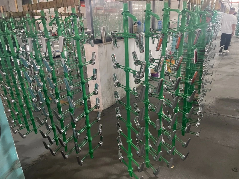
Electroplating depends on electrical current. During the plating process, metal ions in the solution are deposited onto the surface of the workpiece under the action of the electric field.
In theory, the goal is to form a uniform coating on all required surfaces. In actual production, current does not automatically distribute evenly across every area of a complex part. It tends to concentrate on surfaces that are closer to the anode or easier for the electric field to reach.
This is why sharp corners, edges, and protruding areas often receive higher current density. These areas may plate faster, resulting in thicker deposits, rough surfaces, or even burning. At the same time, deep holes, inner cavities, threaded areas, and recessed corners may receive much less current. These areas can suffer from thin plating, poor coverage, or skipped plating.
A well-designed electroplating rack helps reduce this difference. Engineers can adjust the workpiece angle, distance between parts, contact position, and loading pattern to improve current distribution. In some cases, shields, auxiliary anodes, or special conductive structures may also be needed.
The goal is not simply to increase the current. The goal is to guide the current more evenly to the areas that need plating. For production managers, this means fewer rejected parts, more stable coating thickness, and less time spent adjusting process parameters batch by batch.
Why Burning and Thin Plating Happen
Burning usually appears in areas with excessive current density. When metal deposition happens too fast, the local supply of metal ions cannot keep up. The coating may become rough, dark, powdery, or brittle.
This often happens on sharp edges, corners, and surfaces facing the anode directly. If the rack layout makes some parts too close to the anode, or if the spacing between parts is too narrow, local current concentration can become more serious.
Thin plating is the opposite problem. It appears in areas where the current is too weak or where the surface is shielded by the part geometry. Deep holes, blind holes, grooves, and internal corners are common problem areas.
In many cases, both problems can happen on the same part. The outer edges are over-plated, while the inner areas are under-plated. The part may look acceptable from the outside, but hidden areas may not have enough coating thickness to meet corrosion resistance requirements.
This is one reason why rack design is especially important for automotive parts, sanitary hardware, precision components, and functional metal parts that require stable coating thickness and long-term corrosion resistance.
Solution Flow Also Affects Plating Quality
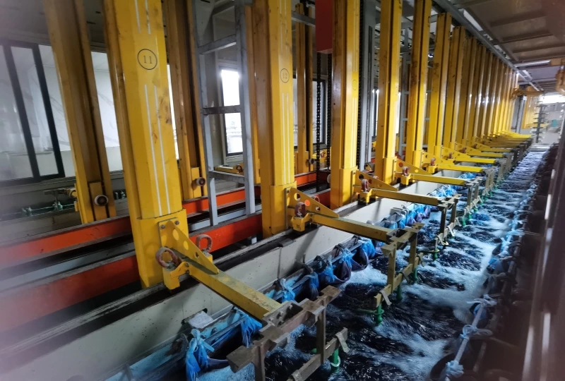
Electroplating is not only an electrical process. It is also a mass transfer process.
Metal ions, additives, and other chemical components in the plating bath must continuously reach the surface of the workpiece. If the solution around a certain area becomes stagnant, metal ions may be consumed faster than they are replenished.
When this happens, the coating may become dull, rough, uneven, or poorly bonded. The bath condition in the main tank may look normal, but the local condition near the workpiece surface can be very different.
The rack layout has a direct influence on solution flow. If parts are loaded too densely, the plating solution cannot circulate freely between them. If the rack structure blocks the flow path, dead zones may form behind the workpieces. In these areas, the solution cannot refresh quickly enough.
This problem becomes more serious on high-speed automatic electroplating lines. The production cycle is shorter, and each process step must be more stable. A rack that works acceptably in a small manual line may not perform well in a high-capacity automatic rack plating line.
Good rack design should allow the solution to reach all important surfaces of the part. It should also avoid unnecessary blocking, overcrowding, and enclosed spaces where the solution cannot circulate properly.
Gas Release Is Critical for Complex Parts
During electroplating, gas bubbles may form on the surface of the workpiece. If these bubbles stay trapped in holes, grooves, or recessed areas, they can block the plating solution from contacting the surface.
The result may be skipped plating, pitting, small uncoated spots, or poor surface appearance.
For some complex parts, the main problem is not always insufficient current. It may be poor gas release. A small change in hanging angle can sometimes make a big difference. If the part is positioned so that bubbles can naturally rise and escape, plating coverage becomes more stable.
This is why workpiece orientation should be considered during rack design. The rack should not only hold the part securely. It should also help air and hydrogen bubbles leave the surface as quickly as possible.
For parts with blind holes, threaded holes, U-shaped areas, or internal corners, the direction of gas release should be checked before mass production. Otherwise, the same plating defect may appear repeatedly in the same position.
Drainage and Drag-Out Affect Operating Cost
Rack design also affects drainage when the rack moves from one tank to another.
If the rack or workpiece geometry traps too much solution, the line will carry plating chemicals into the next rinse tank or process tank. This is called drag-out. Excessive drag-out increases chemical consumption, increases wastewater treatment load, and may contaminate following tanks.
For example, if nickel solution is carried into the rinse section in large amounts, the rinse water becomes contaminated more quickly. If chemicals are carried into another functional tank, they may affect the stability of the next process.
Good rack design should help the solution drain quickly and consistently. The hanging angle, part direction, rack frame shape, and spacing between parts should all support smooth drainage.
Reducing drag-out does not only save chemicals. It also helps improve process stability and reduce the risk of cross-contamination in the electroplating line.
Loading Density: More Parts Is Not Always Better
Many factories want to increase the number of parts on each rack to improve production capacity. This is understandable. Higher loading can reduce handling time and improve equipment utilization.
However, more parts per rack does not always mean higher real output.
If the parts are too close to each other, they may shield one another from current and solution flow. Some areas may receive too much current, while other areas receive too little. The coating may become uneven, and the reject rate may increase.
Dense loading can also make it harder for gas bubbles to escape and for solution to drain. As a result, the factory may produce more parts per cycle, but also generate more rework and scrap.
The best rack design is not the one that holds the largest possible number of parts. It is the one that balances loading capacity, coating uniformity, process stability, and acceptable yield.
Before increasing loading density, manufacturers should check whether the required coating thickness, appearance, adhesion, and corrosion resistance can still be maintained across all parts and all rack positions.
Mechanical Stability Matters in Automatic Plating Lines
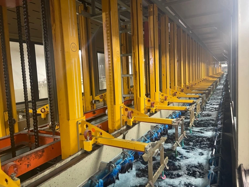
In automatic electroplating production, racks are repeatedly lifted, transferred, immersed, and moved between tanks. They must withstand mechanical movement, liquid resistance, vibration, and long-term chemical exposure.
If a rack is not rigid enough, the workpieces may shift or swing during operation. Even a small change in position can affect the distance between the workpiece and the anode. This changes local current density and solution flow.
The result may be inconsistent coating thickness between different parts on the same rack, or unstable quality between batches.
This is especially important for precision parts and decorative components. A small difference in coating thickness or surface brightness may lead to rejection by the customer.
A reliable electroplating rack should have enough mechanical strength to maintain its shape during repeated production cycles. It should also match the movement method of the automatic plating line, including lifting, transfer, positioning, and unloading.
Rack Insulation and Maintenance Should Be Checked Regularly
The insulation layer of the rack is another important factor. In most rack designs, only selected contact points should conduct electricity to the workpiece. Other areas of the rack are usually insulated to prevent unnecessary metal deposition.
If the insulation layer becomes cracked, worn, or peeled, exposed metal areas on the rack may start to receive plating. This wastes current and plating metal. It also changes the original current distribution and may affect coating thickness on the workpieces.
As unwanted deposits build up on the rack, the rack becomes heavier and harder to clean. Electrical contact may become unstable, and the plating process may become less predictable.
For this reason, regular rack inspection and maintenance should be part of normal electroplating line management. Factories should check contact points, insulation condition, deformation, corrosion, and accumulated deposits before they affect production quality.
Key Points for Selecting or Designing Electroplating Racks
When selecting or designing racks for a rack plating line, manufacturers should consider more than the size of the workpiece.
The following points are especially important:
-
Workpiece geometry
Parts with holes, threads, grooves, sharp edges, or internal cavities usually require special rack design. -
Coating thickness requirement
If the customer has strict thickness tolerance or corrosion resistance requirements, current distribution must be carefully controlled. -
Contact position
The contact point should provide stable conductivity while avoiding unacceptable marks on visible or functional surfaces. -
Part spacing
Enough spacing is needed to reduce shielding and allow solution circulation. -
Hanging angle
The part should be positioned to help gas bubbles escape and allow solution to drain. -
Loading weight
The rack must be strong enough to carry the full load without deformation. -
Automation level
Automatic lines require racks with better dimensional stability, repeatability, and compatibility with the transfer system. -
Maintenance and insulation
The rack should be easy to inspect, clean, repair, and maintain over long-term use.
When Should You Review or Redesign the Plating Rack?
A plating rack should be reviewed when the same quality problems appear repeatedly, even after the bath chemistry and electrical parameters have been adjusted.
In general, manufacturers should check the rack design when they face the following situations:
-
Coating thickness varies greatly between different areas of the same part
-
Edges are easily burned while inner areas remain under-plated
-
Holes, grooves, or recessed surfaces have poor coverage
-
Air bubbles are often trapped during plating
-
Parts move or swing during automatic line transfer
-
The rack carries too much solution from one tank to another
-
Loading quantity increases, but the reject rate also increases
-
A new part is being introduced into an existing rack plating line
In these cases, changing only the plating time or current setting may not solve the root problem. The rack, part orientation, contact point, spacing, anode arrangement, and tank movement should be evaluated together.
Rack Design Should Be Considered Early in New Plating Line Projects
One common mistake is to consider rack design only after plating defects appear. By that time, the production line may already be running, and changes can be more difficult.
For new electroplating projects, rack design should be discussed during the early engineering stage, together with tank layout, automation level, process sequence, anode arrangement, production capacity, and overall electroplating production line cost.
This is especially important for custom electroplating lines. A rack plating line is not only a group of tanks and hoists. The rack, anode system, rectifier, tank size, transfer system, process time, and control system all work together as one production system.
When these factors are designed together, the plating line is more likely to achieve stable coating quality, higher yield, and lower long-term operating cost.
Conclusion
Electroplating racks may look simple, but they have a direct influence on plating yield and coating quality.
A properly designed rack helps current reach the workpiece more evenly, improves solution flow, allows gas bubbles to escape, reduces drag-out, and keeps parts stable during production. A poorly designed rack can cause burning, thin plating, skipped plating, rough surfaces, poor drainage, unstable coating thickness, and unnecessary rework.
For manufacturers using rack plating for automotive parts, hardware, bathroom fittings, electronics, mechanical parts, or precision metal components, rack design should be treated as a key process factor.
If you are planning a new rack electroplating line or need to improve the yield of an existing plating process, Autoplatingtec can help evaluate the workpiece structure, loading method, rack design, and automatic line configuration.
Send us your part drawings, photos, coating requirements, and production capacity target. Our engineering team can help recommend a suitable electroplating line solution for your production needs.