English
 Español
Electroplating Rectifier Selection: 7 Checks Before Ordering
An electroplating rectifier converts incoming AC power into the controlled DC power used by the plating process. Choosing one involves more than matching the current rating printed on a quotation.
The power supply must suit the actual load, bath requirements, current-delivery system and production controls. A unit with sufficient rated amperage can still be unsuitable if its operating voltage, regulation range, cooling or communication functions do not match the line.
Use these seven checks when discussing rectifier configuration for a new electroplating line or an equipment upgrade.
1. Calculate Current from the Simultaneous Plated Area
Begin with the surface area connected to each independently regulated output and the current density specified for the approved process.
Required process current (A) = Plated surface area (dm²) × Process current density (A/dm²)
For illustration, a load with 200 dm² of plated surface area operating at 3 A/dm² requires:
200 × 3 = 600 A
These figures demonstrate the calculation; they are not recommended settings for a particular coating.
Count every part connected to the same output at the same time. Include exposed conductive fixture area where applicable, and review both the smallest normal load and the largest planned load. Part weight or pieces per rack alone does not establish the electrical demand.
The final rating should account for the approved operating range, continuous duty, site conditions and defined expansion plans. Any reserve capacity should have an identified purpose.
For the wider relationship between loading, tank occupancy and production rate, see our electroplating line capacity calculation guide.
2. Check the Voltage Required at the Operating Current
The required output voltage depends on the process and the complete electrical circuit. Review bath conditions, electrode arrangement, anode-to-cathode distance and losses through busbars, cables and contacts.
A long connection route or a deteriorated contact can consume part of the available voltage before it reaches the plating load. Rectifier location and the DC connection layout therefore belong in the same engineering review.MUNK
Ask the supplier to confirm the continuous current-and-voltage operating envelope. Maximum current and maximum voltage listed separately do not, by themselves, establish the output available at every operating point.
Define the required conditions at the rectifier terminals and the expected conditions at the tank connections.
3. Specify Regulation, Ripple and Any Special Waveform
Constant-current control adjusts voltage to maintain the selected current within the power supply’s limits. Constant-voltage control maintains the selected voltage while current responds to circuit conditions.
Specify the required operating mode, adjustment range, accuracy and limits. Where current is set from load area, the recipe must use the area actually connected.
Residual ripple is the varying component remaining in the DC output. A displayed average current does not fully describe that waveform. Ask how ripple is defined and measured, and request performance data at representative production loads.MUNK
The acceptable ripple level should follow the coating process requirements. One percentage copied from another application is not a complete specification.
If pulse or pulse-reverse operation is required, agree on the waveform and suitable hardware with the process supplier before equipment selection.
4. Review the Current Path for Rack or Barrel Production
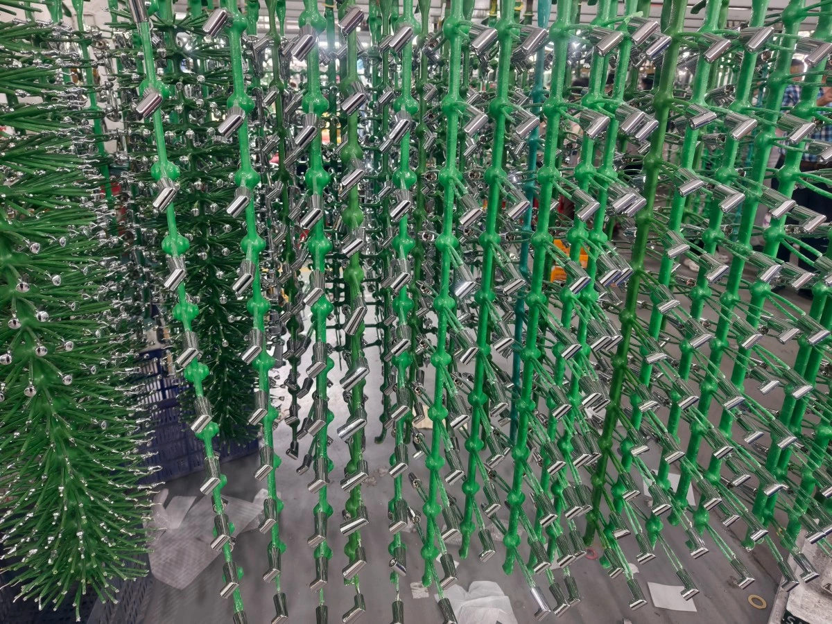
On a rack electroplating line, the current path includes busbars, carrier contacts, rack hooks and individual part contacts. Their arrangement and condition affect how current reaches the workpieces.
On a barrel electroplating line, review the specified contact system together with barrel loading, rotation and part movement.
The rectifier regulates its output; it does not independently establish uniform current distribution over every workpiece. Contact maintenance, fixture design, electrode arrangement and bath operation remain part of the process.
Include inspection and cleaning access for the current-delivery components in the layout review.
5. Match Cooling and Installation to the Workshop
Compare cooling options against the real installation conditions.
For an air-cooled unit, confirm the permitted ambient temperature, ventilation clearances, airflow route and maintenance access. For a water-cooled unit, confirm coolant temperature, flow, pressure, water quality and heat-rejection requirements.
Request the continuous rating at the expected site conditions, including any temperature-related derating. Also agree on the enclosure protection, location relative to chemical mist, cable entry and access needed for servicing.FlexKraft
A suitable cooling arrangement must be available during production, not only during an initial trial.
6. Define the PLC Interface and Actual Feedback
An automatic line needs a clear agreement on how the PLC and rectifier exchange commands and operating information.
Specify which functions are included:
- Output enable and stop commands
- Current or voltage setpoints and operating-mode selection
- Actual current and voltage feedback
- Ready, running and fault status
- Communication-loss response and restart permissions
- Current ramps, charge counting or batch records where required
Confirm whether signals use hardwired connections or an agreed industrial communication protocol. The supplier should identify the exact interface, signal scaling and data available.
A command sent by the PLC does not confirm that the requested output was achieved. Acceptance checks should compare commands with measured feedback. Our electroplating line PLC control guide explains how these functions connect with line operation.
7. Agree on Performance Checks and Service Scope
Before ordering, define how the proposed configuration will be verified.
The test plan should identify representative operating points, test loads, instruments, tolerances and records. Include the agreed checks for current and voltage regulation, ripple, remote commands, feedback and fault response.
Separate equipment testing from wet-process validation. A power supply demonstration does not establish coating thickness distribution or finished-part quality under production conditions. Those results require the agreed chemistry, representative parts, loading arrangement and process tests.
Also confirm manuals, circuit diagrams, parameter backups, spare parts, warranty conditions and the procedure for replacing a failed module or complete unit.
Information to Prepare for a Rectifier Quotation
Use the following checklist to give equipment suppliers a common basis for their proposals.
| Information | Details to provide |
|---|---|
| Process | Coating system, approved current-density range and required waveform |
| Load | Part drawings, plated surface area, minimum and maximum loading |
| Electrical zones | Loads operating simultaneously and outputs requiring independent control |
| Output requirements | Current range, voltage range, duty and agreed regulation requirements |
| Current delivery | Rack or barrel contacts, busbar route and connection distances |
| Site conditions | Incoming power, ambient conditions, installation location and available cooling |
| Automation | PLC interface, commands, feedback, alarms and record requirements |
| Acceptance and service | Test conditions, documentation, spares and support scope |
For an existing line, include rectifier nameplates, circuit information and available operating records. Document the production issue or planned capacity change that the upgrade must address.
Frequently Asked Questions
How do I calculate the current needed for electroplating?
Multiply the simultaneous plated surface area connected to one regulated output by the approved process current density, using consistent units. Review exposed fixture area and actual loading. Final equipment selection must also consider voltage, duty, operating range and site conditions.
Can the same rectifier specification serve different plating processes?
Some power supplies can operate across several applications, but suitability depends on the required current, voltage, waveform, regulation and control functions. Each proposed process should be checked against the unit’s documented capabilities.
Does a higher current rating automatically increase line output?
No. Production rate also depends on the approved process, loading, plating time, tank availability and transfer schedule. Additional current capacity is useful only when the process and the rest of the line can use it appropriately.
Can an existing rectifier be connected to a new PLC?
This depends on its available control interface and feedback signals. Review the exact model, documentation and required functions. Any proposed interface conversion should be included in the engineering scope and tested.
Discuss the Power Requirements for Your Plating Line
AutoPlatingTec supplies customized electroplating lines for rack and barrel production. Rectifier configuration should be reviewed together with the process tanks, loading method, current-delivery system and automation requirements.
Planning a new line or upgrading existing equipment? Contact our team with your part information, coating requirements, production target and available site data to discuss the equipment configuration.