English
 Español
Small Automatic Rack Electroplating Line for Hardware Parts
A custom-engineered linear rack plating system for small and medium-sized hardware parts requiring controlled pretreatment, rinsing, copper, nickel and decorative chromium plating.
- Feature
- Linear; Automatic Rack Plating
- Materials
- Copper, Nickel and Decorative Chromium Plating
- Application
- Locks, Handles, Bathroom Fittings and Metal Hardware
- Speed
- Project-specific; determined by the approved process cycle
- Max Plated Parts
- Project-specific; confirm L × W × H and maximum rack load
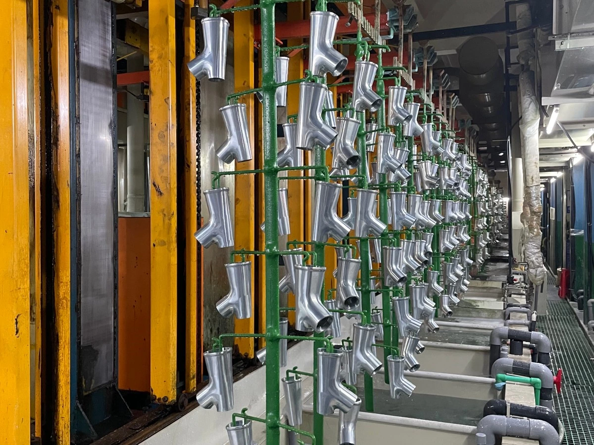
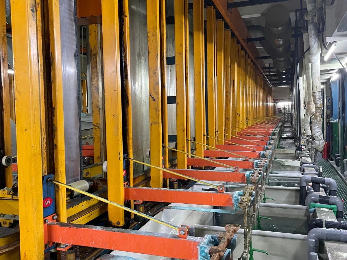
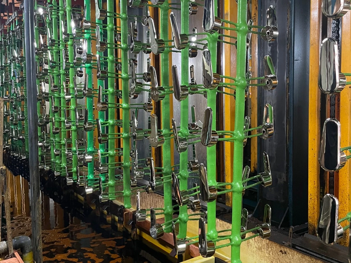
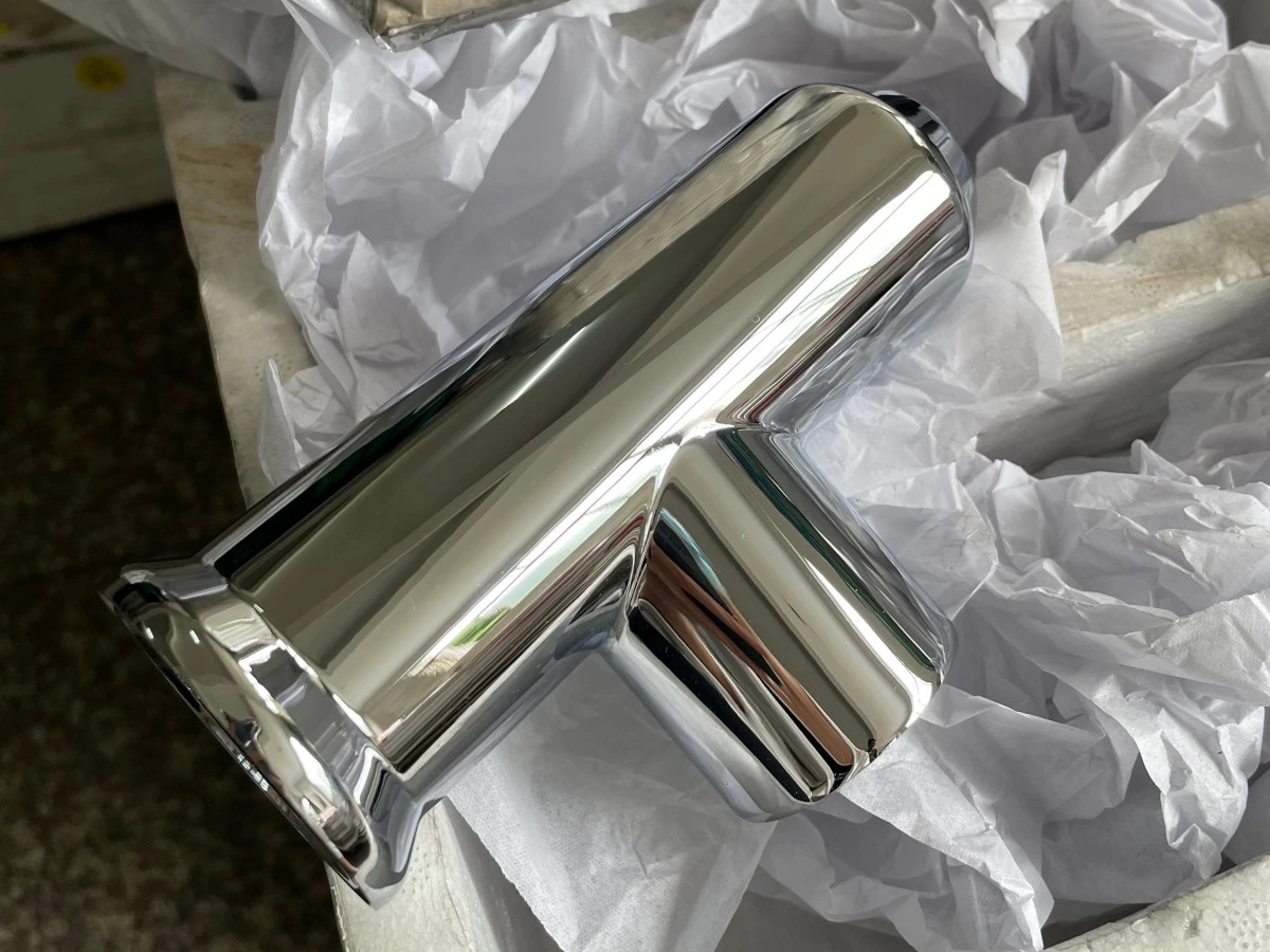
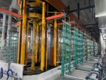
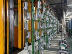
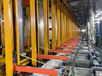
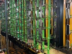

PRODUCT SUMMARY
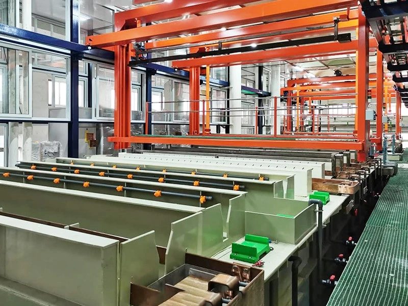
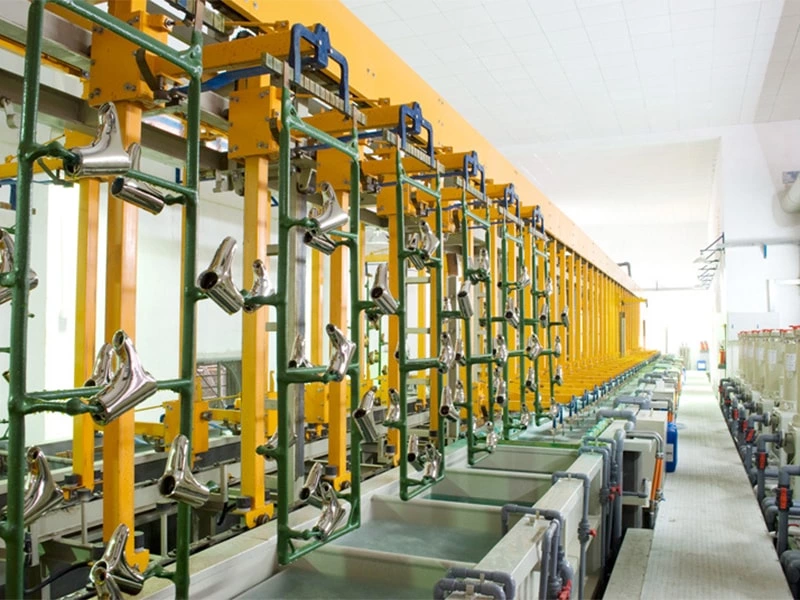
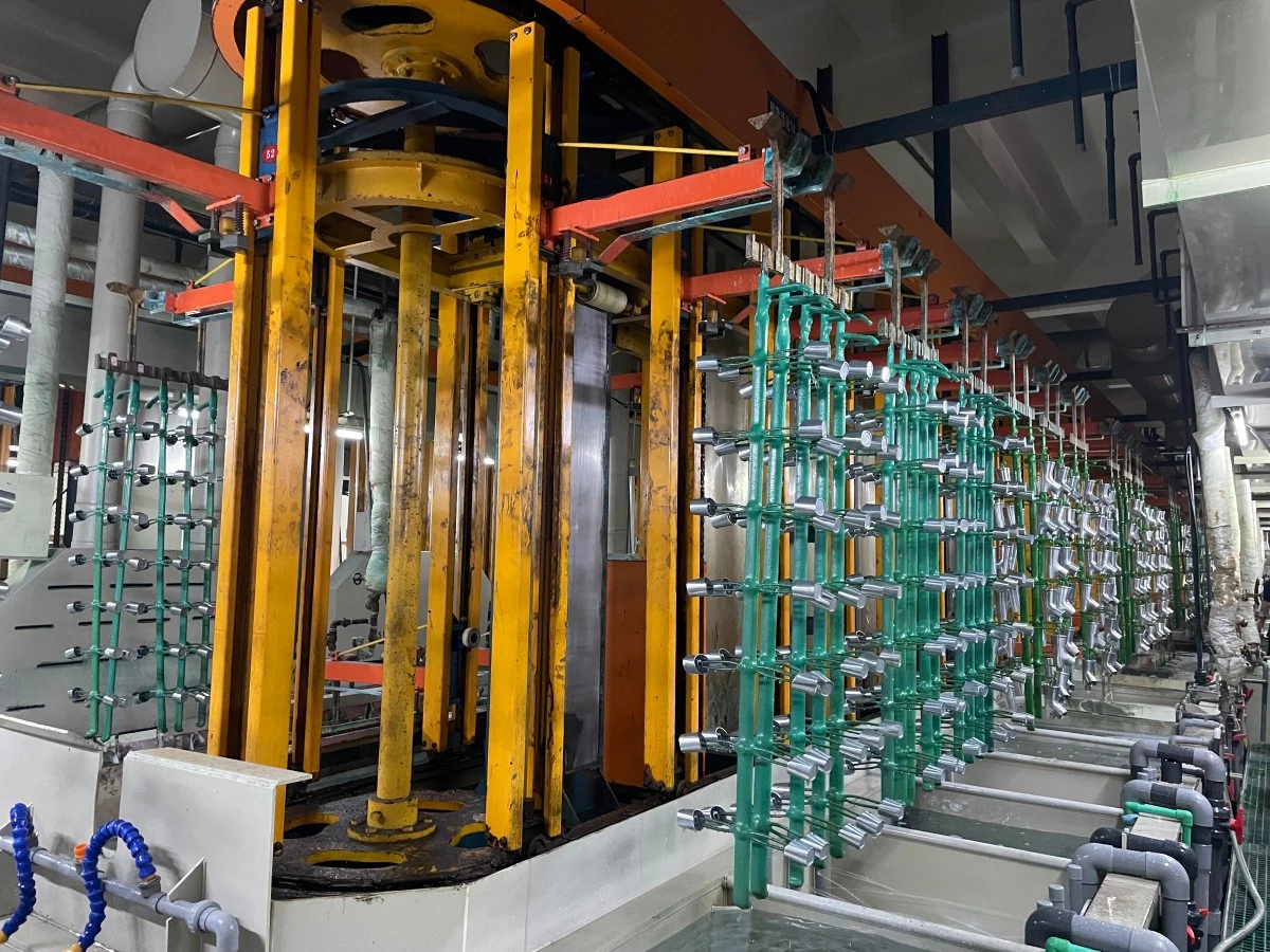
This small automatic rack electroplating line is designed for parts that need to remain individually positioned on racks throughout pretreatment, rinsing and plating. It is suitable for repeat production where electrical contact, part orientation, immersion time and transfer order must be controlled from one load to the next.
The line uses a linear tank arrangement with an automatic rack transfer system. Its process sequence, tank dimensions, rack capacity, rectifier output, filtration, temperature control, exhaust collection and control functions are engineered from the actual parts and production target. It is therefore supplied as a project-specific production system rather than a fixed catalogue machine.
This configuration can be considered when the workpiece size, rack load, required output and available workshop space allow a compact linear arrangement.
SUITABLE PARTS AND PLATING SCOPE
Typical applications include:
-
Locks and lock components
-
Door and furniture handles
-
Bathroom fittings and sanitary hardware
-
Decorative metal accessories
-
Tools, brackets and general hardware components
-
Other parts that require stable rack positioning and electrical contact
The primary process scope of this page is copper, nickel and decorative chromium plating. The exact pretreatment and coating sequence must be confirmed from the substrate, surface condition, corrosion-resistance requirement, appearance standard and specified coating thickness.
Zinc, tin, silver, hard chromium, plastic plating and aluminum anodizing are evaluated as separate process configurations. They should not be assumed to use the same tanks, pretreatment, ventilation or production arrangement as a copper–nickel–chromium line.
CONFIGURATION AT A GLANCE
| System Section | Function | Project Definition |
|---|---|---|
| Loading and rack stations | Hold and position parts for processing | Rack size, contact points, loading quantity and maximum weight |
| Pretreatment and rinse tanks | Prepare the substrate and control carryover | Bath sequence, tank quantity, rinse method and water demand |
| Plating tanks | Provide the specified coating layers | Chemistry, tank dimensions, anode arrangement and operating temperature |
| Automatic transfer system | Lift and move racks through the approved sequence | Hoist quantity, lifting load, travel distance, dwell time and drip time |
| Rectifiers and busbars | Supply controlled DC power to plating stations | Current, voltage, control method, connection and cooling requirements |
| Filtration and circulation | Maintain bath circulation and remove suspended contamination | Flow rate, filter type, pump material and maintenance access |
| Heating and cooling | Maintain the required bath temperature | Heat load, heater or heat exchanger type and control range |
| Exhaust collection | Capture process fumes at the tanks | Hood arrangement, airflow, duct routing and scrubber interface |
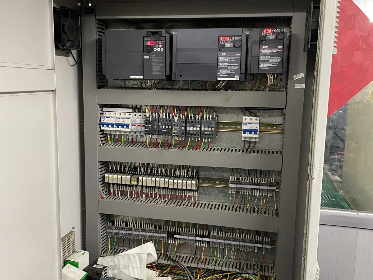
| Control system | Coordinate transfer, timing, alarms and operating status | PLC/HMI functions, operating modes, interlocks and data requirements |
| Utility interfaces | Connect the line to factory services | Power, water, compressed air, exhaust and wastewater connections |
HOW THE LINE OPERATES
-
Operators load the parts onto a suitable rack and confirm that the contact points and orientation match the approved loading method.
-
The transfer system moves the rack through the programmed pretreatment, rinse and plating sequence. Dwell time, transfer order and drip time are set according to the approved process.
-
Rectifiers and auxiliary equipment operate according to the requirements of each active tank. The agreed control package can display equipment status, process timing and alarm conditions.
-
After the final rinse and specified post-treatment, the rack returns to the unloading position for part removal and quality inspection.
The final operating sequence is developed from the customer’s approved process. A generic sequence should not be used as a substitute for trial results or the chemical supplier’s process requirements.
MAIN ENGINEERING OPTIONS
Depending on the project, the line can be configured with:
-
One or more automatic transfer hoists
-
Automatic, semi-automatic and maintenance operating functions
-
Custom racks and cathode contact arrangements
-
Tank heating, cooling, agitation, circulation and filtration
-
Individual rectifiers for the required plating stations
-
Tank exhaust hoods, PP or FRP ducting and a scrubber connection
-
Counterflow or project-specific rinsing arrangements
-
PLC/HMI control, equipment interlocks and alarm records
-
Loading, unloading, drying or post-treatment stations
-
Safety guarding, access platforms and maintenance space
Each option is included only when it is required by the process, capacity calculation, factory layout and local safety or environmental requirements.
PROJECT-SPECIFIC TECHNICAL DATA
The following values must be confirmed before the equipment configuration and quotation are finalized:
| Technical Item | Required Project Basis |
|---|---|
| Workpiece envelope | Maximum part length × width × height |
| Part and rack weight | Maximum weight per rack, including fixtures |
| Rack loading | Parts per rack and rack spacing |
| Production target | Parts per hour, racks per hour or parts per shift |
| Substrate | Steel, copper alloy, zinc alloy or other confirmed material |
| Coating specification | Layer sequence, thickness, appearance and test standard |
| Process sequence | Pretreatment, rinses, plating stages and post-treatment |
| Tank dimensions | Calculated from rack clearance, immersion depth and bath volume |
| Transfer equipment | Hoist quantity, load, travel, lifting height and timing |
| Rectifier capacity | Required current density, effective plating area and operating voltage |
| Temperature control | Bath temperature, heat load and cooling demand |
| Control scope | Automatic functions, permissions, alarms, recipes and data interfaces |
| Workshop limits | Available footprint, clear height and maintenance access |
| Utilities | Power supply, water, compressed air, exhaust and wastewater conditions |
For early capacity planning, see our electroplating line capacity calculation guide.
TYPICAL SCOPE OF SUPPLY
A project scope may include:
-
Process, rinse and recovery tanks
-
Rack transfer hoist and supporting structure
-
Cathode bars, busbars and electrical connections
-
Rectifiers for the specified plating stations
-
Pumps, filters and circulation pipework
-
Heating or cooling equipment where required
-
Exhaust hoods and connections to the gas treatment system
-
Electrical cabinet, PLC/HMI and field controls
-
Platforms, guarding and maintenance access
-
Factory assembly, functional checks and agreed documentation
Chemical formulations, wastewater treatment, building work, utility supply and on-site installation responsibilities must be clearly defined in the commercial and technical proposal.
WHY USE A RACK CONFIGURATION?
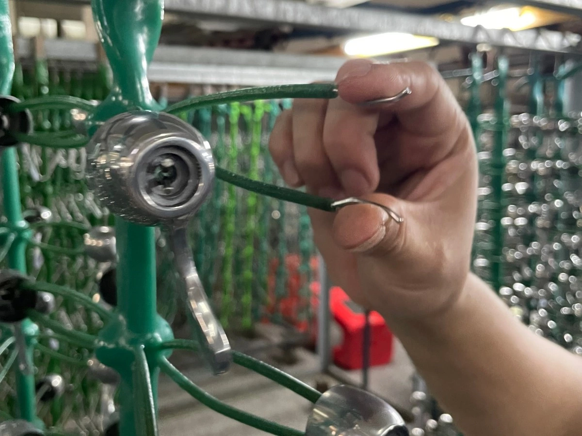
A rack line holds each part in a defined position and provides a controlled electrical contact point. This makes it suitable for components whose visible surfaces, geometry or finish requirements do not allow uncontrolled part-to-part contact during plating.
The correct choice still depends on part geometry, coating specification, rack density, production output and handling requirements. For wider project planning considerations, read our automatic rack electroplating line planning guide.
INFORMATION REQUIRED FOR A QUOTATION
Please provide:
-
Part drawings or clear photographs with dimensions
-
Substrate material and current surface condition
-
Required coating sequence and thickness
-
Appearance, corrosion and adhesion requirements
-
Parts per rack and required production output
-
Available workshop dimensions and clear height
-
Local power supply and available utilities
-
Required automation, traceability and data functions
-
Exhaust, wastewater and local compliance requirements
With this information, the process route, tank quantity, rack arrangement, hoist schedule, rectifier capacity and auxiliary systems can be evaluated as one complete line.
FACTORY ACCEPTANCE AND DELIVERY
Before shipment, the agreed mechanical movement, control sequence, operating modes, alarms, interlocks and documentation can be checked during a Factory Acceptance Test. Any wet test, simulated load, customer-supplied parts or process demonstration must be defined in the contract because these items affect the FAT scope and preparation.
See our guide to the Factory Acceptance Test for electroplating lines.
FAQ
Is this a standard electroplating machine?
No fixed configuration is used for every project. The tanks, racks, transfer system, rectifiers, controls and auxiliary equipment are selected from the actual parts, process sequence, output target and factory layout.
What parts are suitable for this small automatic rack plating line?
It is intended for small and medium-sized hardware parts that need controlled orientation and reliable electrical contact, such as locks, handles, bathroom fittings and decorative metal components. Final suitability depends on the part geometry, substrate, rack design and coating requirement.
Can the line be designed for copper, nickel and chromium plating?
Yes. A copper–nickel–decorative chromium process can be engineered after the substrate, pretreatment, coating thickness, appearance standard and production target are confirmed.
Can the same line also be used for zinc, tin, hard chrome or anodizing?
These processes have different chemistry, pretreatment, tank, rectifier, ventilation and handling requirements. They must be reviewed as separate process configurations. They should not be added to the scope only because the workpieces are similar in size.
How is production capacity calculated?
Capacity depends on parts per rack, loading interval, tank dwell times, transfer conflicts, hoist quantity and operating efficiency. It should be calculated from the complete production cycle rather than from a single travel-speed figure.
What information is needed to prepare a proposal?
Please send part drawings or photographs, dimensions, substrate, coating specification, parts per rack, target output, available floor space, utility conditions and required control functions.
Can the equipment be tested before shipment?
Yes. The agreed mechanical and control functions can be checked during FAT. The exact test conditions, acceptance criteria and required customer materials should be confirmed before manufacturing is completed.
REQUEST A TECHNICAL PROPOSAL
Send us your part drawings, substrate, coating sequence, output target and available factory space. Our engineering team will evaluate the suitable process route, rack arrangement, tank configuration, transfer system, rectifier capacity, controls and auxiliary equipment for your project.
Request a Quote
If you are interested in our products and want to know more details,please leave a message here,we will reply you as soon as we can.