English
 Español
How to Plan an Automatic Rack Electroplating Line
An automatic rack electroplating line is not simply a row of process tanks connected by hoists. It is a coordinated production system in which workpieces, racks, transfer equipment, tanks, utilities, controls, exhaust collection, and operator access must work together. If one element is planned in isolation, the finished line may face unstable loading, difficult maintenance, excessive carryover, or limited flexibility when new parts are introduced.
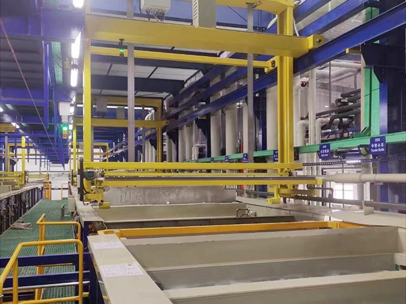
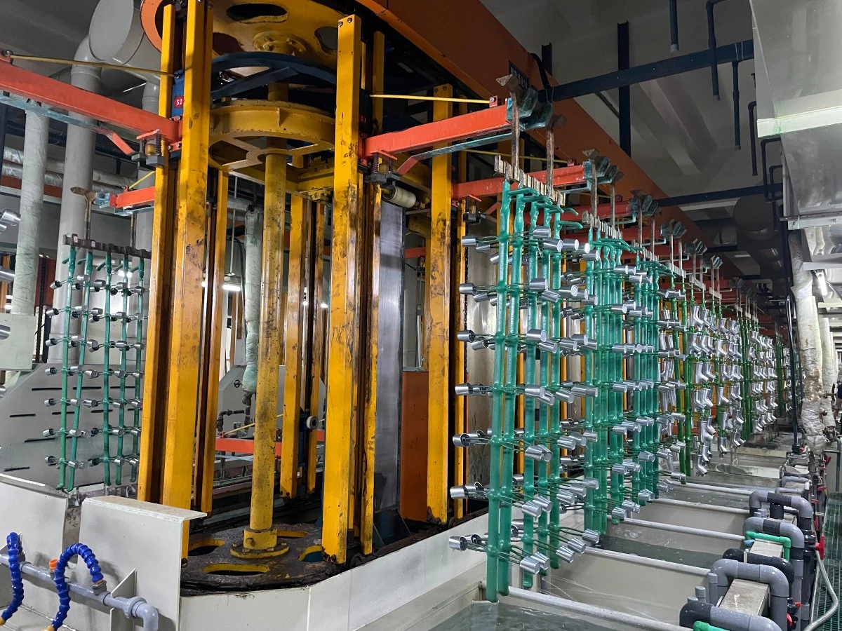
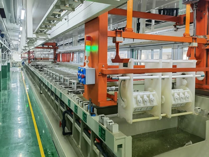
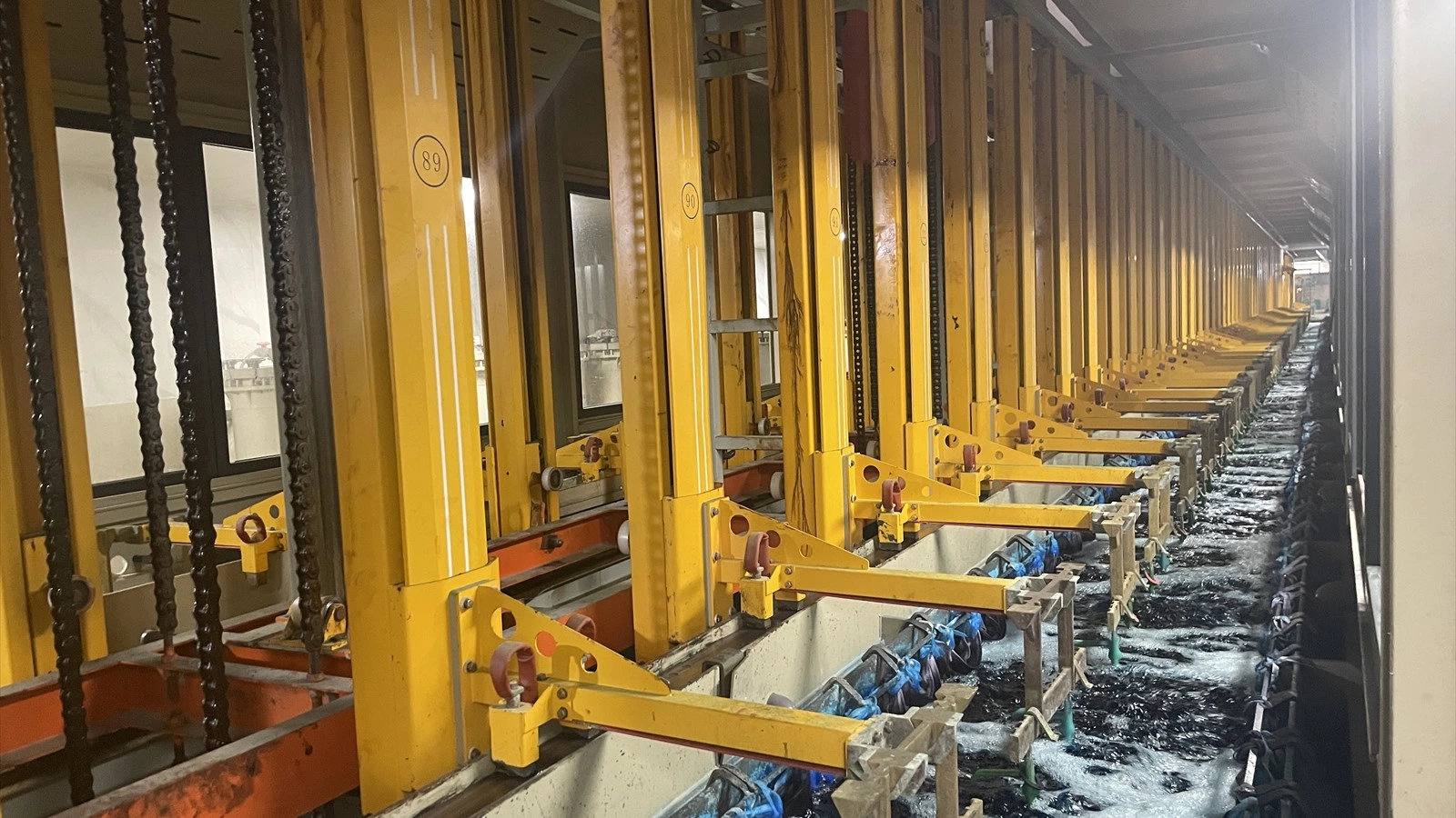
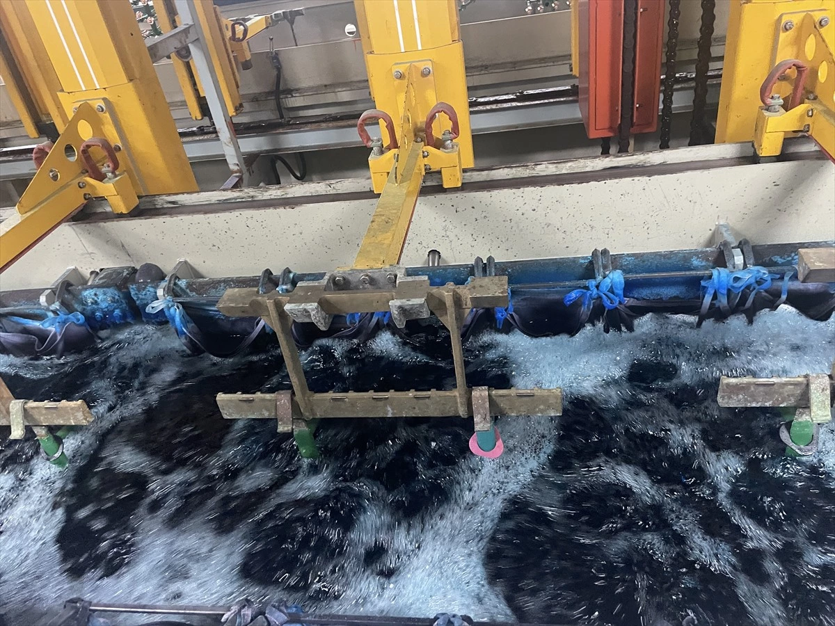
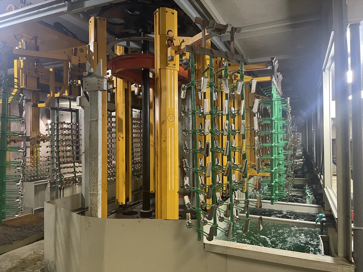
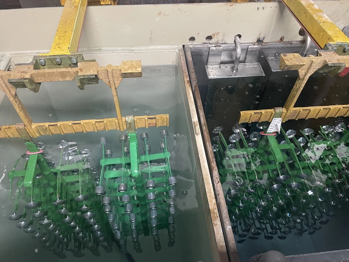
The equipment shown in the accompanying production photographs illustrates several visible features of a rack-based line: repeated vertical lifting stations, long tank sequences, suspended workpiece racks, and active solution movement. These images are useful for discussing system layout, but they do not identify a specific plating chemistry or confirm process parameters. Bath composition, dwell time, temperature, electrical settings, and material selection must always be verified for the actual parts and coating specification.
1. Start with Workpiece and Production Data
Line planning should begin with the parts, not with a standard equipment drawing. Engineers need representative part drawings or samples, substrate information, required coating system, acceptable contact marks, quality criteria, expected production volume, shift pattern, and product mix.
Projects involving zinc or zinc-nickel coatings also need a clearly defined coating specification, post-treatment route, part-loading method, and embrittlement-control requirement. See our automatic zinc and zinc-nickel electroplating line specification guide.
Part dimensions alone are not enough. Weight, shape, openings, recessed surfaces, drainage paths, and areas that can trap gas or solution all affect how the workpiece should be positioned. The rack must fit the part securely while maintaining electrical contact and enough clearance for solution circulation. A family of similar parts may share one rack concept, while a frequently changing product mix may require more adaptable loading arrangements.
This data helps determine whether the project needs a linear gantry, vertical lifting annular, or customized configuration. Autoplatingtec provides several categories of rack electroplating line solutions that can be evaluated against the actual production requirement.
2. Match the Rack to the Transfer System

In an automatic line, the rack is both a workholding fixture and a moving interface. Its upper support, pickup position, balance, stiffness, and loaded weight must be compatible with the lifting and transfer mechanism. A rack that performs adequately in a manual tank may not remain stable during repeated automatic lifting, travel, positioning, and immersion.
The transfer concept should be reviewed with the rack fully loaded. Engineers should consider whether the load can swing, whether the pickup point remains repeatable, and whether the rack can enter each tank without contacting tank walls, anodes, pipes, or covers. Consistent positioning helps maintain predictable workpiece-to-anode relationships and reduces the risk of mechanical interference.
For projects with many small or medium-sized workpieces, a vertical lifting annular electroplating production line may provide a useful reference. For different layouts and process requirements, the transfer arrangement should be engineered around the plant and product data rather than copied from another installation.
3. Define the Process Sequence Before Freezing the Layout
Every required stage should be documented before tank sizes and equipment positions are finalized. The sequence may include preparation, cleaning, activation, plating, intermediate rinsing, final rinsing, and post-treatment, but the exact stages depend on the substrate and finish specification.
A process flow document should identify the purpose of each stage, required residence time, operating window, permissible transfer delay, and any steps that cannot share handling paths. This information becomes the basis for calculating the number of process positions and the movement schedule.
A detailed capacity model should convert the required good-parts output into loads per shift and then verify tank occupancy, rectifier demand and hoist availability.
The physical layout must also support sensible material flow. Loading and unloading areas should reduce unnecessary handling, while inspection and rework routes should not interrupt normal production. Space for rectifiers, filters, pumps, heating or cooling equipment, chemical storage interfaces, and service access must be considered at the same stage as the tanks.
4. Plan Tank Geometry and Working Clearances Together
Tank length, width, depth, and freeboard should be checked against the complete loaded rack envelope. The working envelope includes the rack frame, workpieces, movement clearance, anode arrangement, solution distribution components, and any internal fixtures. Looking only at the part dimensions can produce a tank that is difficult to operate or maintain.
Clearances should remain adequate at every position, including during entry and exit. Engineers should review how solution displacement changes the liquid level and whether the moving load could create splashing. The structure around the tanks must allow access for inspection, cleaning, pipe maintenance, and replacement of consumable components.
The photographs show a long, closely coordinated row of tanks and lifting mechanisms. Such compact arrangements can use floor space efficiently, but service routes and safe access should not be sacrificed to reduce the footprint.
5. Control Drainage, Carryover, and Rinsing
When a rack leaves a process tank, retained solution travels with the workpieces and fixture. This carryover can increase chemical loss, load the rinse stages, and contaminate the next process step. Workpiece orientation, rack geometry, withdrawal behavior, drainage time, and the route between tanks all influence the amount carried forward.
Parts should be positioned so liquid can drain without forming pockets. Openings and recessed surfaces may require a specific hanging angle. Where the process allows, an appropriate pause above the tank can support drainage before transfer. These decisions should be validated with real parts because two components with similar outer dimensions can retain very different amounts of liquid.
Rinse stages should then be designed for the actual contamination load and quality requirement. Tank arrangement, water introduction, overflow direction, agitation, and control strategy need to work as one system. The goal is not merely to add more rinse tanks, but to create reliable contaminant removal while managing water use and downstream treatment requirements.
6. Evaluate Solution Movement Around the Loaded Rack
Visible surface movement in a tank does not prove that every workpiece area receives adequate solution renewal. Dense loading, broad surfaces, deep recesses, and rack members can create shielded regions. These areas may behave differently from the bulk tank even when the bath appears well mixed.
During trials, engineers should observe how liquid moves through the loaded rack and whether gas can escape from holes, grooves, and enclosed features. The relationship between workpiece spacing, rack orientation, solution movement, and anode location should be evaluated together. Increasing agitation without understanding the flow path may not correct a blocked area.
Rack design has a direct role in this behavior. The article How Electroplating Rack Design Improves Plating Yield and Coating Quality explains how contact, spacing, gas release, and drainage can influence process consistency.
7. Build Controls Around Process Rules and Recovery Needs
Automation should enforce the approved production sequence while giving operators clear information. The control specification may include recipe selection, transfer scheduling, dwell-time management, equipment interlocks, alarms, manual maintenance functions, and production records. The required functions depend on the project and should be agreed before software development.
Abnormal conditions deserve the same attention as normal production. The team should define what happens after a power interruption, blocked movement, sensor fault, or equipment stop. Operators need a safe and understandable recovery procedure that protects both workpieces and equipment.
The interface should present actionable information. Clear station status, alarm location, operating mode, and permitted next actions can reduce troubleshooting time. A gantry rack electroplating production line provides an example of integrated automated transfer and control.
8. Integrate Ventilation, Utilities, and Maintenance Access
Exhaust collection should be coordinated with tank covers, rack travel, operator access, and the building ventilation plan. Duct positions must not interfere with lifting equipment or routine maintenance. The appropriate collection and treatment design depends on the actual process emissions and applicable local requirements.
Autoplatingtec's gas treatment system category shows supporting equipment intended for electroplating exhaust applications. Selection still requires verified airflow, gas characteristics, process schedule, and site conditions.
Utilities should be mapped before installation: electrical supply, water, compressed air where required, heating or cooling, drainage, exhaust, and connections to wastewater treatment. Maintenance teams need access to pumps, valves, filters, sensors, chains, motors, contacts, and tank internals. Components that cannot be reached safely will be harder to inspect and more likely to remain in service beyond their proper maintenance interval.
9. Design for Trials, Changeovers, and Future Products
A new automatic rack electroplating line should not move directly from mechanical completion to unrestricted production. Commissioning should progress through dry movement tests, water trials where appropriate, interlock checks, loaded-rack tests, and controlled process validation. Acceptance criteria should be defined before trials begin.
The trial plan should confirm transfer repeatability, rack stability, clearances, drainage, alarm response, and maintenance access. Validation should use representative parts and agreed quality checks. Results from several rack positions and cycles are more informative than one acceptable sample.
Future changes should also be considered. New workpieces may require different rack spacing, loading weight, process time, or station use. Reasonable allowance in the control structure, transfer capacity, service space, and rack interface can make future adaptation easier. This does not mean oversizing every component; it means identifying likely changes and deliberately engineering the relevant interfaces.
Conclusion
Successful planning of an automatic rack electroplating line depends on coordination. Workpiece data determines rack design; the rack must match the transfer system; the transfer schedule depends on the process sequence; and the tanks, rinsing, controls, exhaust, utilities, and maintenance routes must support the same production plan.
Start with a project brief containing part drawings or samples, substrate and coating requirements, target output, available floor space, utilities, and local environmental constraints. Equipment configuration can then be developed around verified needs rather than assumptions.
If you are evaluating a new line or upgrading an existing system, contact Autoplatingtec with your part information, process requirements, production target, and workshop layout to discuss an appropriate rack electroplating line configuration.