English
 Español
Electroplating Line Capacity Calculation: From Part Data to Tank Count
A request for “20,000 plated parts per day” sounds specific, but it is not enough to size an electroplating line. Twenty thousand small fasteners and twenty thousand decorative handles represent completely different rack or barrel loads, surface areas, process times, electrical demand and handling requirements.
Reliable electroplating line capacity calculation begins with the actual parts and the approved coating process. The calculation must convert the required number of acceptable parts into loads per shift, establish how frequently those loads must enter the line, and then check whether every process tank, hoist, rectifier and supporting system can maintain that production rate.
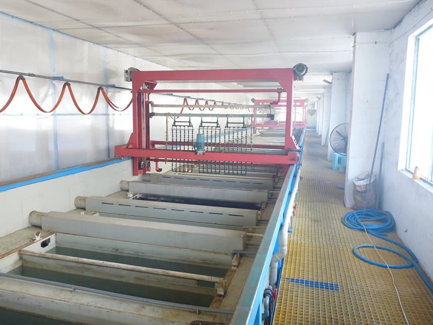
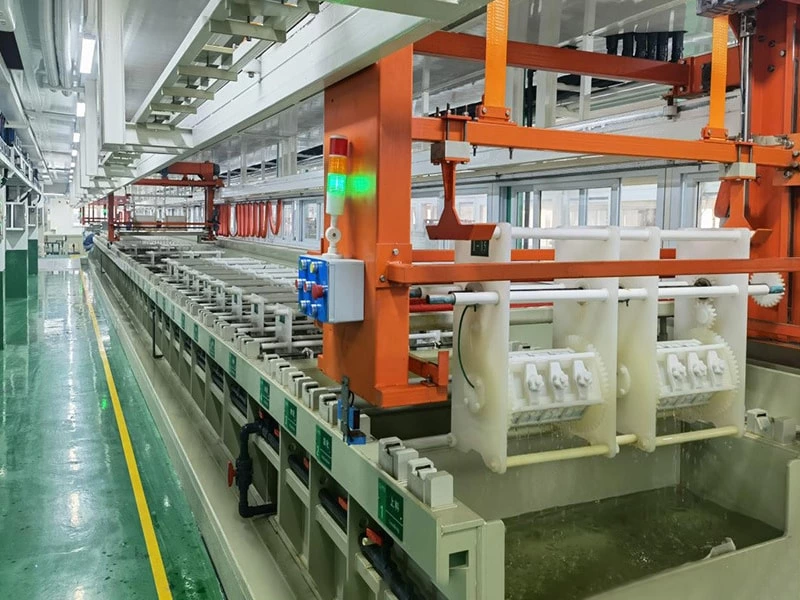
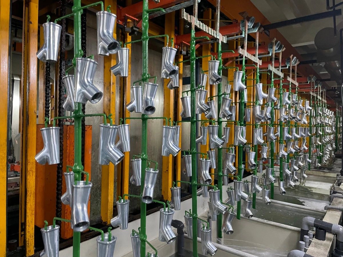
Noted: The following video shows an automatic rack electroplating line in operation and provides a practical view of the equipment layout that must be considered during site preparation.
This guide explains the calculation method used during the early design of automatic rack and barrel plating lines. It also shows why tank volume or annual tonnage alone cannot provide a dependable capacity figure.
For a wider review of workpiece data, process sequence, transfer equipment, controls and environmental systems, see our automatic rack electroplating line planning guide.
1. Define What “Capacity” Means for the Project
Before calculating equipment size, the project team should agree on the unit used to express production capacity.
Depending on the products, capacity may be stated as:
-
Acceptable parts per hour or shift
-
Racks or barrels processed per hour
-
Plated surface area per shift
-
Kilograms processed per shift
-
Batches completed per day
-
A defined monthly product mix
Good parts per shift is normally the most useful commercial measure, but it should be supported by loads per hour and plated surface area. Weight can be helpful for barrel-plated components, although weight alone does not show the electrical load or the number of parts that can move freely inside a barrel.
The time basis also has to be clear. An eight-hour shift does not always provide eight hours of production. Loading, unloading, breaks, product changes, bath analysis, maintenance and planned cleaning may reduce the time available for steady operation.
A useful capacity statement therefore identifies:
-
The representative part or part family
-
The required number of acceptable parts
-
The number and length of production shifts
-
The approved loading method
-
The expected quality yield
-
The operating time included in the calculation
Without these definitions, two suppliers can quote the same nominal capacity while proposing very different equipment.
2. Build a Part-Family Data Sheet
A plating line should not be calculated from one convenient sample if the factory intends to process several products. Create a part-family data sheet that includes normal products as well as the parts that create the highest process demand.
| Required input | Why it affects capacity |
|---|---|
| Part number and base material | Determines the applicable pretreatment and coating route |
| Overall dimensions and unit mass | Affects rack layout, barrel loading, tank clearance and hoist load |
| Estimated plated surface area | Determines current demand and contributes to drag-out |
| Holes, recesses, tubes and folded areas | Can affect drainage, solution exchange and loading orientation |
| Coating system and thickness | Determines the required process sequence and deposition time |
| Daily or monthly quantity | Establishes the production demand |
| Shift pattern | Defines the available operating time |
| Parts per rack or mass per barrel | Converts part demand into load demand |
| Incoming surface condition | May change cleaning, activation and pickling time |
| Appearance and contact limits | Influence rack density and permitted handling |
| Product changes and lot separation | Add changeover and scheduling requirements |
The physically largest part is not always the capacity bottleneck. A smaller part may have more plated surface area per load, require a longer deposit time, fit fewer pieces on a rack because of orientation, or require a separate post-treatment route.
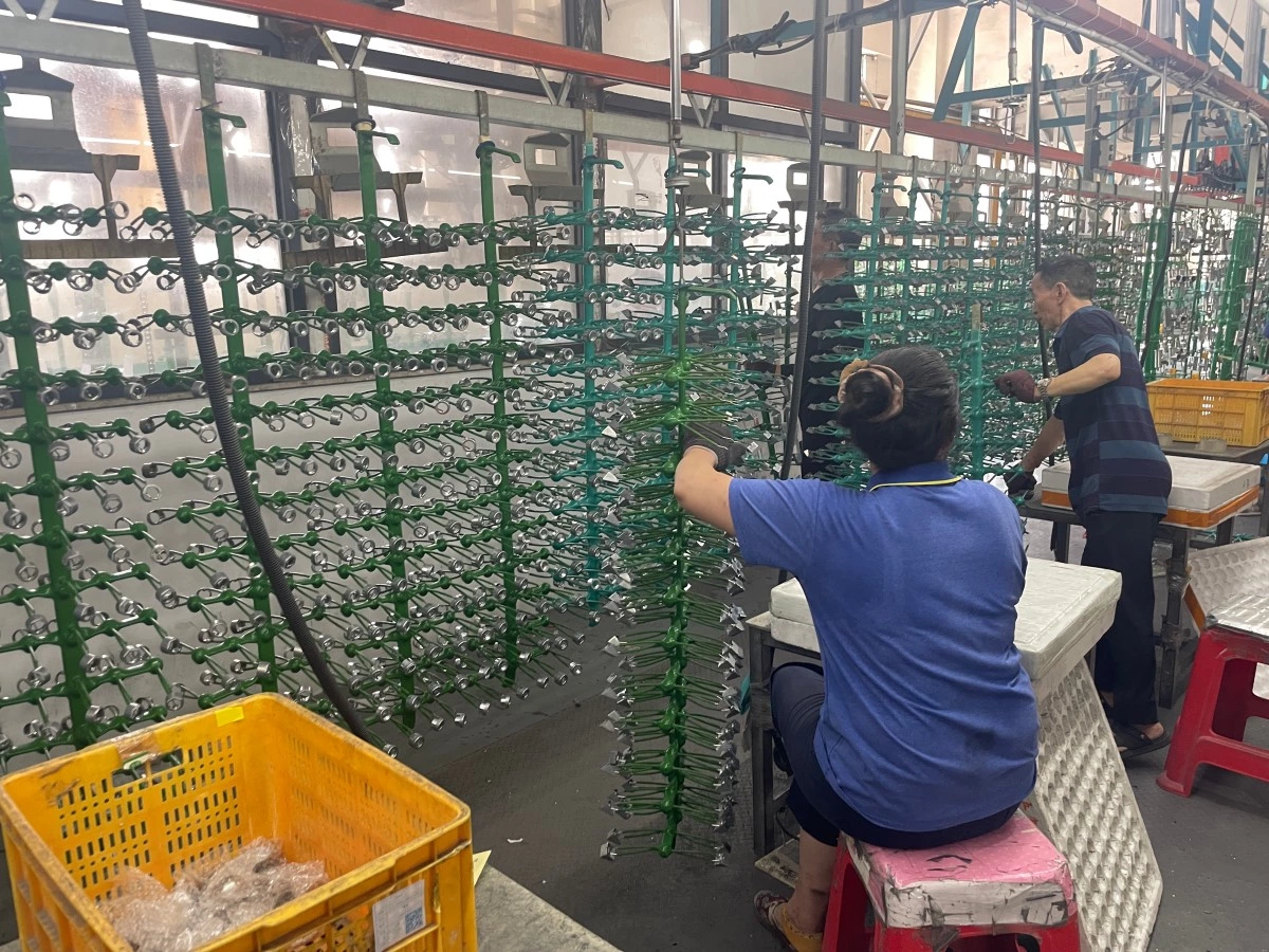
Representative sample parts are valuable during this stage. A loading trial can reveal nesting, tangling, weak electrical contacts, trapped solution and collision risks that may not be obvious from drawings. For rack projects, our electroplating rack design guide explains how spacing, orientation, contact and drainage affect usable rack capacity.
3. Convert the Production Target into Loads per Shift
Once the number of parts per rack or barrel has been verified, production demand can be converted into load demand.
Required processed loads per shift = Good-parts target ÷ (Parts per load × Expected first-pass yield)
The result should then be compared with the net operating time:
Required dispatch interval = Net operating minutes per shift ÷ Required processed loads per shift
The dispatch interval is the time available between launching two successive racks or barrels into the line.
Consider a simplified example:
-
Target output: 12,000 acceptable parts per shift
-
Loading quantity: 50 parts per rack
-
Expected first-pass yield: 96%
-
Net steady-production time: 420 minutes per shift
Required processed loads:
12,000 ÷ (50 × 0.96) = 250 racks per shift
Required dispatch interval:
420 ÷ 250 = 1.68 minutes per rack
The line therefore has to accept approximately one rack every 1.68 minutes during steady production.
This example is only an initial demand calculation. It does not prove that the proposed process tanks and transfer system can achieve the interval. That requires a stage-by-stage cycle model.
Availability and yield should also be handled consistently. If planned downtime has already been removed from the net operating minutes, it should not be deducted a second time through another general efficiency factor.
4. Calculate Rack and Barrel Loads Differently
The loading method changes the basis of the capacity calculation.
A rack electroplating line holds parts individually. The designer must confirm the number of parts per rack, loaded dimensions, total surface area, rack weight, electrical contact, drainage orientation and clearance from tanks, anodes, hoods and transfer equipment.
Increasing the number of parts on a rack does not always increase useful capacity. Crowded parts may shield one another, restrict solution movement, worsen current distribution or increase retained solution. If a higher loading density reduces coating consistency or first-pass yield, the apparent capacity gain may disappear.
A barrel electroplating line processes multiple small parts as a bulk load. Barrel capacity must consider:
-
Recommended fill level
-
Total part weight
-
Total plated surface area
-
Barrel and hoist load limits
-
Electrical contact through the load
-
Part movement and solution exchange
-
Risk of nesting, tangling or lodging in perforations
-
Impact damage and thread protection
-
Loading, draining and unloading time
Kilograms per barrel should not be selected only from the mechanical capacity of the equipment. A barrel may be able to lift a heavier load while the parts inside no longer move, contact or plate correctly.
5. Use Process Times to Find the Bottleneck
List every stage in the approved process sequence and record its target time as well as any permitted minimum and maximum time.
Typical stages include:
-
Loading
-
Cleaning and electrocleaning
-
Rinsing
-
Pickling or activation
-
Plating
-
Recovery rinsing
-
Passivation or conversion coating
-
Sealing or topcoating
-
Drying or baking
-
Cooling and unloading
The longest process time is often an important bottleneck, but it is not the only one. A shorter stage can also restrict output if it has only one available position, a narrow timing window or a long transfer movement.
For an initial steady-state check:
Required simultaneous load positions = Process residence time ÷ Dispatch interval, rounded up to the next whole number
Using the earlier example, assume the required plating time is 12 minutes and the dispatch interval is 1.68 minutes:
12 ÷ 1.68 = 7.14
The simplified model therefore requires at least eight simultaneous plating-load positions.
This does not automatically mean eight separate physical tanks. The final arrangement depends on how many independently controlled load positions each tank can accept, the anode and rectifier arrangement, electrical isolation, workpiece clearance, transfer access and the approved process. Transfer and drain time must also be included in the detailed schedule.
Adding parallel plating positions will not solve a bottleneck at loading, activation, passivation, drying or unloading. Every stage has to support the same required launch rate.
6. Model the Hoist and Transfer Cycle
Tank occupancy and hoist availability must be calculated together. A layout can contain enough tanks and still miss the required production rate because the transfer system cannot complete all moves within the available time.
The transfer model should include:
-
Pickup and positioning time
-
Vertical lifting and lowering time
-
Horizontal travel time
-
Drain or drip time
-
Rack or barrel engagement time
-
Loading and unloading time
-
Empty return movements
-
Restricted movement and collision zones
-
Minimum and maximum process-time windows
-
Recovery procedures after an alarm or stopped move
A loaded carrier cannot simply wait wherever the scheduling model finds spare time. Excessive delay between certain stages can affect the surface condition, while leaving a load in a process tank beyond its approved time may damage the finish.
Adding a second hoist also does not automatically double capacity. Hoists sharing a track can block one another, require protected crossing zones or compete for the same loading and process stations. Their routes should be simulated using the actual tank spacing and movement rules.
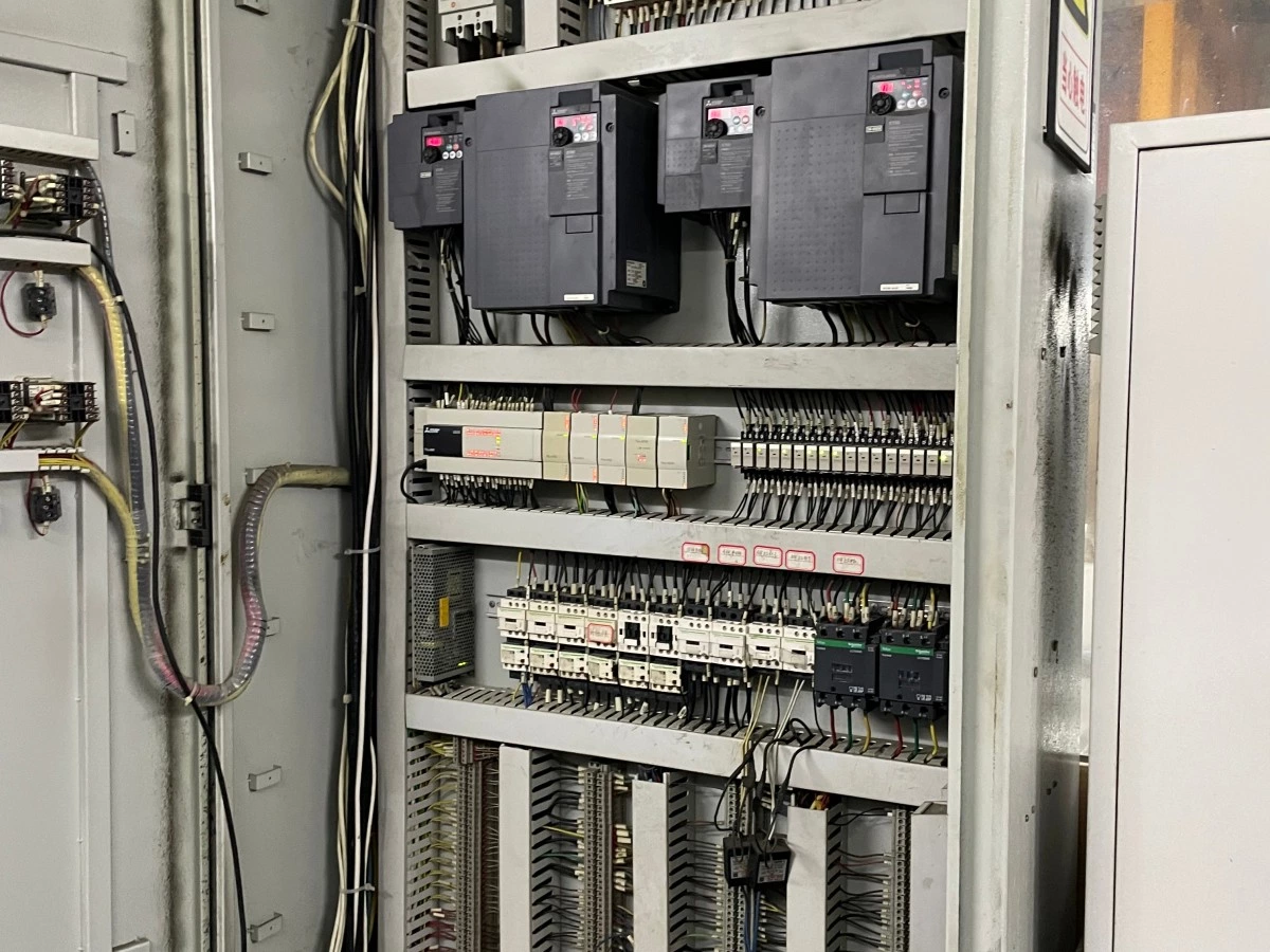
The control program should be developed from the approved production schedule rather than after the mechanical layout has been finalized. Recipes, load identification, dwell-time limits, transfer priorities and fault recovery all influence achievable output.
7. Size Rectifiers from Surface Area, Not Piece Count
The DC current required for a plating load is calculated from the total active cathode surface area in an electrical zone and the approved process current density.
Required DC current = Total plated surface area per electrical zone × Approved current density
The units must be consistent. For example, surface area expressed in square decimeters must be paired with current density expressed in amperes per square decimeter.
The calculation should consider all parts connected simultaneously, together with exposed rack, contact or auxiliary cathode area where applicable. The required current-density range must come from the approved process specification or chemistry supplier. It should not be copied from an unrelated coating line.
Rectifier selection must also consider:
-
Required output-voltage range
-
Anode-to-cathode distance
-
Solution conductivity and bath resistance
-
Busbar, cable and contact voltage losses
-
Rack or barrel current-delivery method
-
Current ramps, pulse requirements or ampere-hour control
-
Cooling method and ambient conditions
-
Simultaneous operation of parallel plating positions
-
Monitoring, alarms and production records
A rectifier with sufficient total amperage can still give poor results if current distribution, contacts, electrode arrangement or control are unsuitable for the loaded parts.
8. Check the Capacity of Supporting Systems
The main transfer line is only one part of the production system. Supporting equipment must be sized from the same load model.
Rinsing and wastewater
More loads per hour normally carry more process solution into the rinse system. Drag-out per load, rinse stage arrangement and target rinse quality should be used to determine water and wastewater demand. The method is explained in our electroplating rinse system design guide.
Filtration and bath circulation
Filter and circulation systems should match bath volume, process requirements and expected contamination load. A nominal pump flow does not confirm that the solution will move correctly around a fully loaded rack or barrel.
Heating and cooling
Calculations should include startup requirements, tank heat loss, workpiece loading, ventilation losses and heat generated by the process. A system that maintains temperature during an empty trial may not hold the same temperature at full production.
Exhaust collection
Exhaust requirements are based on the actual baths, temperatures, surface areas, agitation, hood arrangement and applicable local requirements. The branch ducts, main duct, fan and electroplating gas treatment system should be engineered as one system.
Drying and baking
Dryers and ovens need enough positions or conveyor residence time for the required launch rate. Batch ovens can create queues when the batch size, loading interval and required treatment cycle are not coordinated with the plating line.
Site utilities
Power, water, drainage, heating, cooling, compressed air and environmental systems must support simultaneous production. Use the electroplating line site-preparation checklist to coordinate these interfaces before installation.
9. Apply Realistic Operating Factors
A theoretical schedule assumes that every load arrives on time and every machine remains available. A production estimate must also account for how the factory will actually operate.
Review time required for:
-
Rack or barrel loading and unloading
-
Product and recipe changes
-
Bath sampling and chemical additions
-
Filter and pump maintenance
-
Rack contact cleaning and repair
-
Anode maintenance
-
Tank cleaning
-
Planned production breaks
-
Quality inspection and lot release
-
Alarm recovery and minor stops
-
Preventive maintenance
Do not apply one unexplained efficiency percentage to every project. Separate the assumptions for equipment availability, operating speed and quality yield so that each one can be reviewed.
Planned reserve capacity should also have a defined purpose. It may be needed for future demand, maintenance coverage, seasonal peaks or an expected product family. An arbitrary percentage added without checking the process bottleneck may increase the cost of the wrong part of the line.
10. Test the Real Product Mix
A factory rarely runs one identical part continuously for a full year. Capacity should therefore be tested against representative production scenarios.
Useful scenarios include:
-
Highest-volume product
-
Lowest number of parts per rack
-
Highest plated surface area per load
-
Longest plating time
-
Most restrictive process-time window
-
Heaviest rack or barrel
-
Product requiring a separate passivation or topcoat
-
Product with the longest drying or baking cycle
-
Peak mixed-production week
-
Planned future product family
Avoid calculating the complete line from an average part that does not actually exist. Averages can hide the product that consumes the most tank positions, rectifier current or hoist time.
For mixed production, the capacity model should state the assumed sequence and number of loads for each family. It should also include changeovers, dedicated tanks and any restrictions on running different chemistries or finishes at the same time.
11. Define How Capacity Will Be Verified
A supplier’s technical proposal should show more than a final parts-per-day figure. The capacity basis should be traceable through the equipment design.
Useful design documents include:
-
Approved process sequence
-
Part-family and production table
-
Rack or barrel loading drawing
-
Parts and plated surface area per load
-
Process-time table
-
Required launch interval
-
Tank and station occupancy calculation
-
Hoist movement schedule or simulation
-
Rectifier loading calculation
-
Utility and supporting-equipment schedule
-
Capacity assumptions and exclusions
-
Maintenance and future-expansion strategy
A Factory Acceptance Test for the electroplating line can verify dry-cycle movement, timing, controls, interlocks and agreed equipment functions before shipment. Final wet-process capacity and coating performance normally require the approved chemistry, utilities, production racks or barrels, representative parts and agreed quality tests at the installation site.
The contract should define capacity in measurable terms. For example, it can identify the named product, acceptable parts per shift, loading quantity, coating specification, operating hours, permitted downtime and quality acceptance criteria. “High output” or “mass production” is not a testable performance requirement.
12. Information to Send with an Initial RFQ
To prepare an initial electroplating line capacity calculation, provide:
-
Part drawings and clear photographs
-
Base material and incoming surface condition
-
Dimensions and unit weight
-
Estimated plated surface area
-
Coating system, thickness and applicable specification
-
Passivation, sealer, topcoat, drying or baking requirements
-
Quantity by part family
-
Number and length of production shifts
-
Preferred rack or barrel loading method
-
Existing racks, barrels or sample parts where available
-
Permitted contact areas and handling marks
-
Workshop dimensions and available installation area
-
Available utilities and environmental requirements
-
Expected future products or capacity increase
If some information is not yet available, identify it as an open item. That is more useful than allowing each potential supplier to make a different hidden assumption.
Conclusion
Electroplating line capacity is not determined by tank size, annual tonnage or plating time alone. It comes from the relationship between good-parts demand, parts per load, process-time windows, simultaneous tank positions, hoist movements, electrical demand, supporting equipment and realistic operating conditions.
The correct sequence is to define the parts and coating process, convert the production target into a required load interval, calculate the occupancy of every stage, and then test whether the complete line can maintain that interval.
If you are planning a new rack or barrel plating project, contact Autoplatingtec with your part drawings, coating requirements, production targets, preferred loading method and workshop information. Our engineering team can review the capacity basis and line configuration as one complete system.
Frequently Asked Questions
Can electroplating line capacity be calculated from parts per day?
Parts per day is a starting point, but it is not sufficient by itself. The calculation also requires parts per rack or barrel, plated surface area, process times, loading and transfer times, operating hours, product mix and expected quality yield.
Is plating time the same as electroplating line cycle time?
No. Plating time is the residence time required in the plating bath. The line cycle or dispatch interval is the time between launching successive loads. Long plating times are commonly supported by several simultaneous load positions.
How many tanks does an automatic electroplating line need?
There is no universal tank count. It depends on the approved process sequence, immersion times, required load interval, number of loads each station can process, rinsing requirements, product mix and maintenance strategy.
Is rack plating or barrel plating better for high production capacity?
Barrel plating can process many small, robust parts in a bulk load, while rack plating provides controlled orientation and separation. Actual capacity depends on the approved loading quantity, surface area, part geometry, process time, handling limits and quality requirement.
Can annual tonnage be used to size a plating line?
Annual tonnage can support an early estimate when the product mix is stable, but it cannot replace part-level data. Loads with the same weight can have very different part counts, surface areas, current requirements and process times.
How much spare capacity should be included?
There is no standard percentage suitable for every project. Spare capacity should be connected to a defined need such as maintenance coverage, seasonal peaks, future product volume or additional coating routes, and then applied to the actual bottleneck.
What should a supplier state when quoting line capacity?
The proposal should identify the representative part family, loading quantity, process sequence, operating hours, launch interval, parallel stations, expected yield, major operating assumptions and the method that will be used to verify performance.