English
 Español
Electroplating Line Site Preparation: Utility and Workshop Checklist
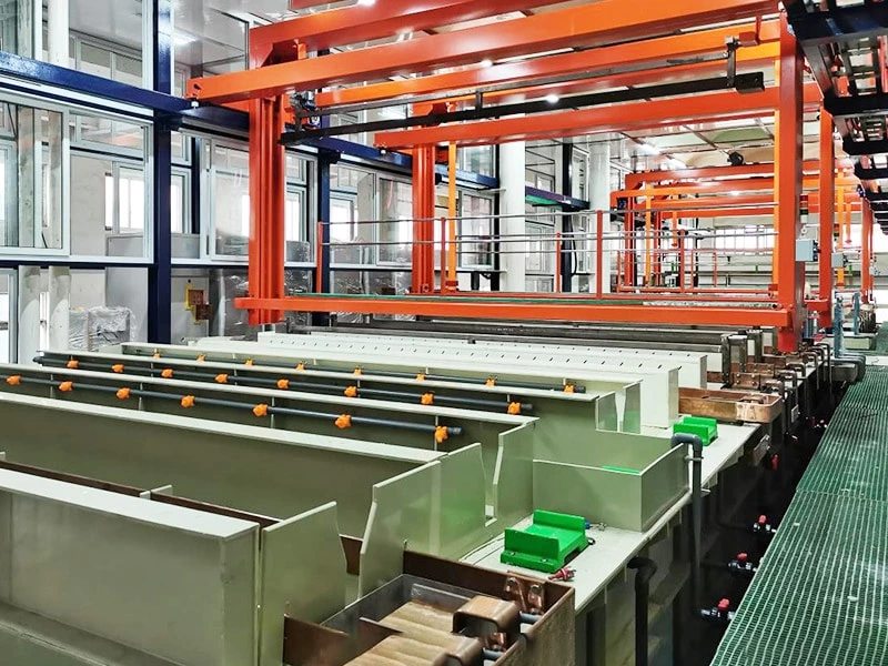
Many delays in a new electroplating line project begin before the equipment reaches the factory. The line may have passed inspection, but commissioning still stops because the main power supply is not ready, the exhaust duct has no clear route, the drainage points do not match the tank positions, or the unloading path is too narrow for the largest module.
Electroplating line site preparation is therefore more than a civil-work task. It requires coordination between the equipment supplier, process engineer, electrical and mechanical contractors, environmental team, and production staff. The exact utility requirements vary with the process chemistry, line capacity, automation level, and local regulations, but the main interfaces should be agreed before equipment fabrication is frozen.
This guide focuses on the site information that should be confirmed before installation. For the earlier equipment-design stage, see our automatic rack electroplating line planning guide.
1. Start with the Supplier's Utility Schedule
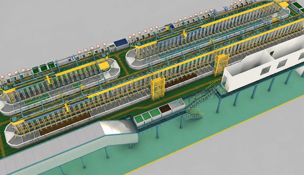
A workshop should not be prepared from the footprint of a similar line or from a preliminary sales drawing. The final site plan needs a utility schedule tied to the approved process sequence and equipment list. It should identify every major consumer and connection point, including rectifiers, heaters, pumps, filters, transfer equipment, dryers, chillers, exhaust fans, scrubbers, control cabinets, and water-treatment equipment.
The schedule should distinguish installed capacity from the loads expected to operate at the same time. It should also show which services are continuous, which are intermittent, and which are only needed during tank filling, maintenance, or startup. Without that distinction, a factory can overbuild one service while leaving another too small for actual production.
| Site interface | Information to confirm before installation |
|---|---|
| Electrical power | Voltage, frequency, phase, connected load, simultaneous load, distribution points, grounding, and isolation |
| Water | Incoming water analysis, required water grades, pressure, continuous flow, tank-filling demand, and storage |
| Drainage and wastewater | Stream segregation, connection points, expected flow and contaminant load, containment, and treatment capacity |
| Exhaust | Bath characteristics, hood arrangement, airflow basis, duct route, make-up air, fan and scrubber location |
| Heating and cooling | Heating method, operating temperature, heat load, supply conditions, condensate return, and heat rejection |
| Compressed air | Pressure, flow, air quality, users, isolation, and whether air contacts the process solution |
| Building and floor | Operating weight, point loads, equipment anchors, floor protection, ceiling height, access, and rigging route |
2. Electrical Supply, Distribution, and Safe Recovery
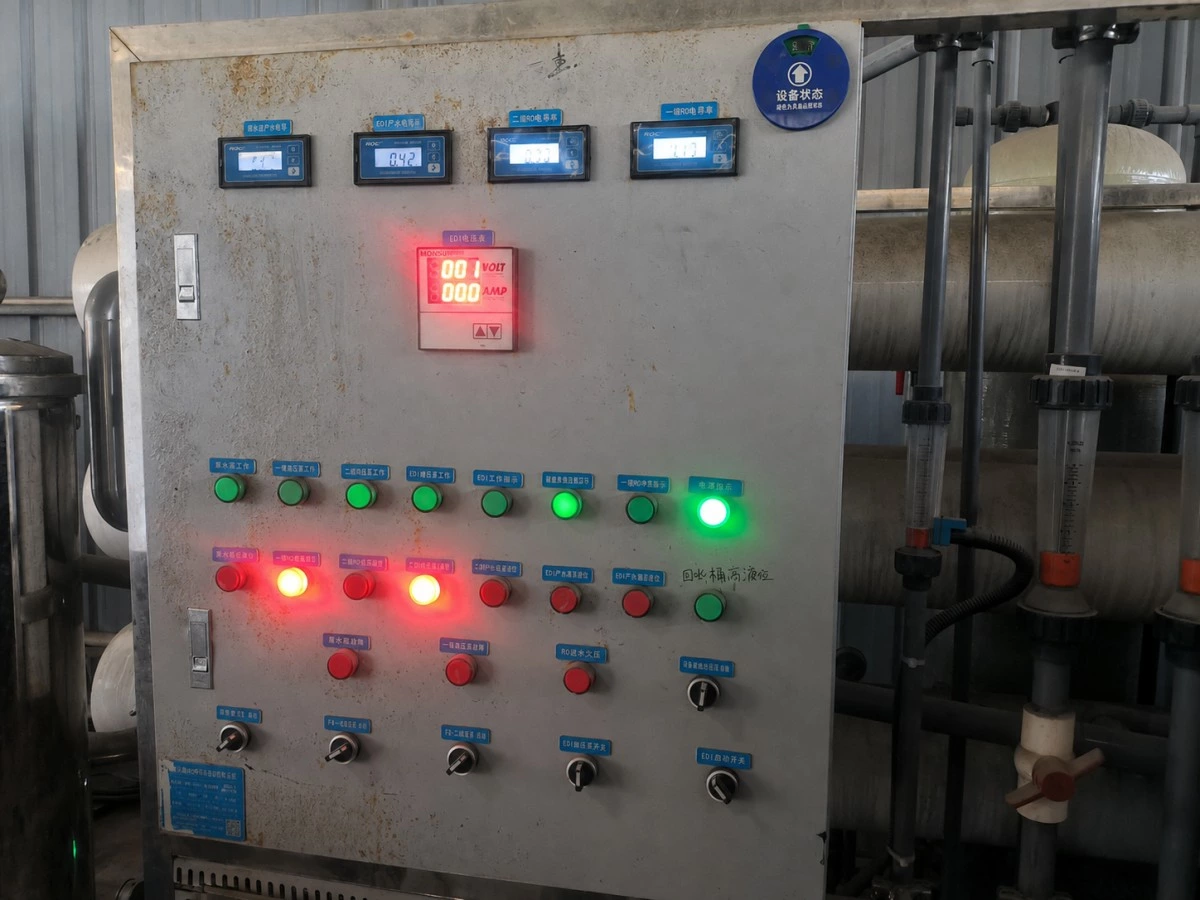
An automatic electroplating line has several different electrical loads. Rectifiers supply the plating current, while motors operate hoists, pumps, fans, and filtration equipment. Heaters, dryers, chillers, and wastewater equipment may add significant demand. The electrical design must therefore be based on the final equipment list rather than the control cabinet alone.
Confirm the available voltage, frequency, phase, transformer capacity, and approved connection points early. The supplier and the customer's electrical engineer should agree on the division between the incoming supply, local isolators, machine distribution, control power, cable trays, grounding, and bonding. Equipment installed in a wet chemical area also requires protective measures selected for the actual environment and local electrical rules.
Power interruption behavior deserves a separate discussion. A backup supply may keep controls and communication alive, but it normally cannot carry the full process load. The team should define how the hoist, rectifiers, pumps, heaters, and timers enter a safe state and how production is recovered after power returns. These recovery sequences should be checked during testing rather than left for operators to discover during an outage.
3. Water Supply: Quality Matters as Much as Flow
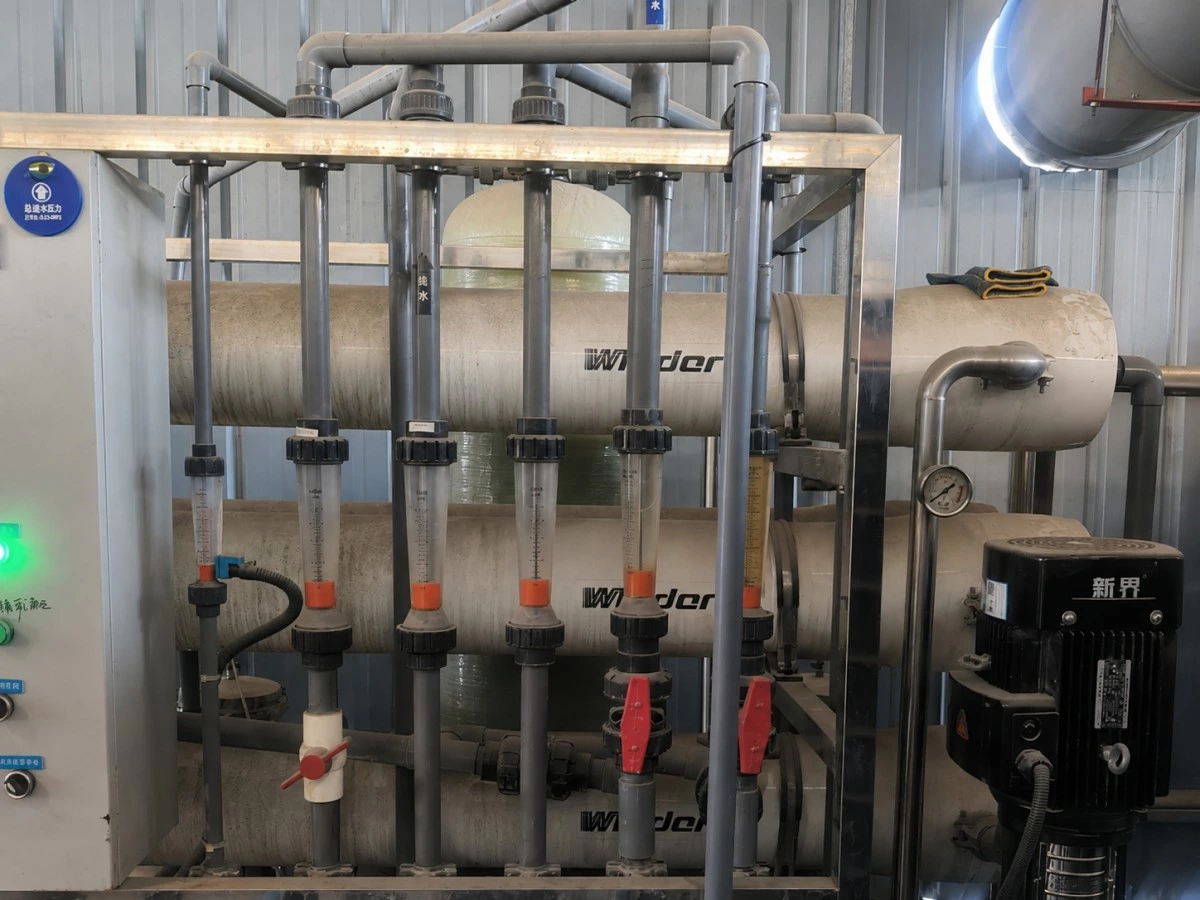
Two factories can have the same water pressure and still need different treatment systems. Hardness, chlorides, dissolved solids, silica, and other constituents can affect bath preparation, rinsing, spotting, and final coating quality. An incoming water analysis should be available before the final rinse and water-treatment design is approved.
The line may use more than one water grade. General rinsing may use an appropriate plant-water or softened-water supply, while bath makeup or final rinsing may require RO or deionized water, depending on the chemistry and finish specification. Supplying the highest water grade to every tank is not automatically better; it can add operating cost without improving the process.
Capacity calculations should separate continuous rinse demand from intermittent tank filling. A supply that can maintain normal rinsing may still take too long to refill a process tank after maintenance. Storage tanks, booster pumps, isolation valves, sample points, flowmeters, and clearly labeled pipe routes should be reviewed as part of the site plan. The relationship between drag-out, rinse stages, and water demand is discussed in our electroplating rinse system design guide.
4. Drainage and the Wastewater-Treatment Interface
A plating-shop drain is not the same as a general factory drain. Process rinses, tank-cleaning liquids, floor wash water, scrubber discharge, and accidental releases may have different treatment requirements. Where different chemistries are present, the wastewater engineer must determine which streams require segregation and which can be combined safely. Incompatible streams should never be connected together simply because they leave the same production line.
The drainage drawing should show the origin, route, destination, and isolation method for each controlled stream. Trenches and collection points need to remain accessible after the tank frames are installed. Curbs, bunds, sumps, leak detection, and emergency holding capacity should be selected according to the process risk and local requirements, not added after wet commissioning begins.
Wastewater capacity must be checked against both hydraulic flow and pollutant load. Reducing rinse-water volume can lower the hydraulic load, but the concentration and treatment sequence still have to be evaluated. The plating line supplier should provide expected process and rinse information, while the local wastewater designer confirms treatment, monitoring, and discharge requirements for the factory.
5. Exhaust Collection, Duct Routing, and Make-Up Air
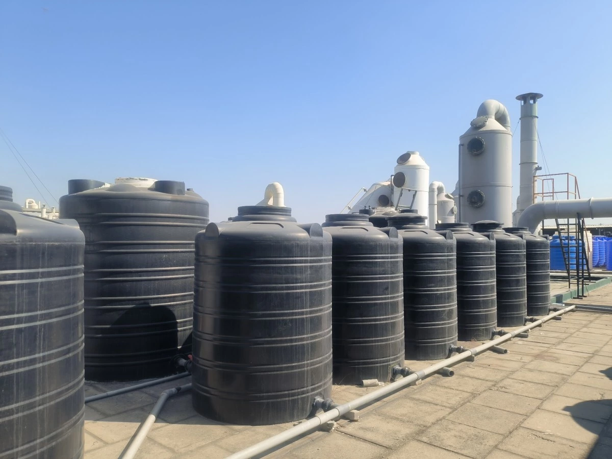
Exhaust requirements depend on bath chemistry, operating temperature, tank surface area, agitation, covers, workpiece movement, and local occupational and environmental rules. A standard airflow copied from another project may not suit the new line. Hood geometry and extraction points should be designed around the actual tanks and transfer movement.
Duct routing must be coordinated with hoist travel, rack clearance, platforms, lights, fire-protection systems, roof structure, and maintenance access. A duct that looks acceptable on a two-dimensional layout can block a motor-removal path or reduce the clear height needed to lift a loaded rack.
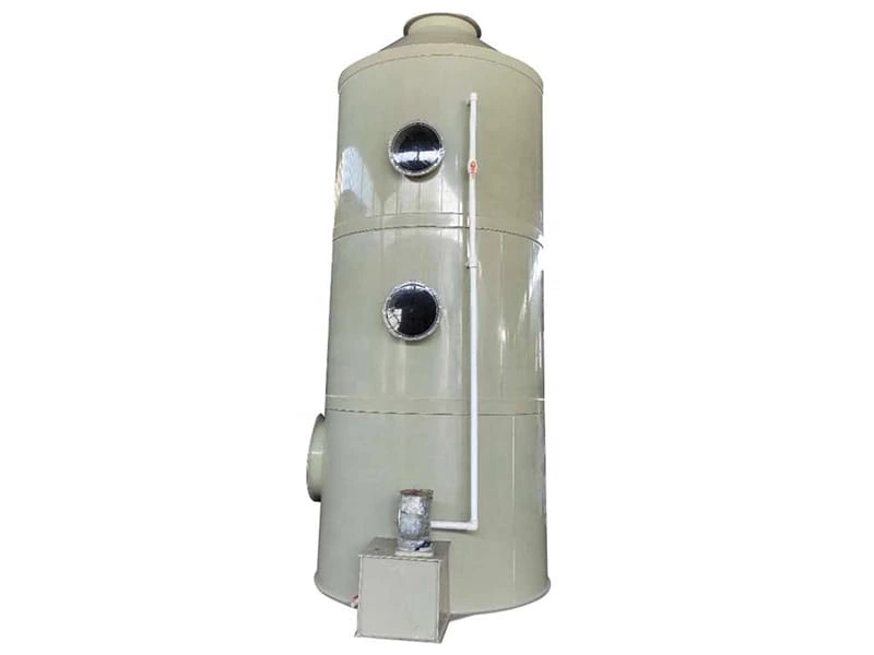
Make-up air is part of the same system. If the workshop cannot replace the air being extracted, door operation, building pressure, hood performance, and operator comfort can all be affected. Fan and scrubber locations also need drainage, electrical power, chemical access, noise consideration, and room for inspection. Autoplatingtec's electroplating gas treatment systems show typical supporting equipment, but the final selection must be based on verified process and site data.
6. Heating, Cooling, and Compressed Air
Process temperature cannot be planned from heater rating alone. The calculation should consider tank volume, operating temperature, startup time, heat loss, workpiece loading, ventilation losses, and heat introduced or removed by the process. Depending on the project, heating may be provided by electric heaters, steam, hot water, or an external heat-exchange system. The selected source determines the required supply conditions, controls, isolation, and, where applicable, condensate handling.
Cooling loads also need a heat-rejection plan. A chiller placed inside a small utility room may move heat out of the bath only to release it into a space that cannot remove it. Confirm the chiller location, ambient conditions, ventilation, cooling-water route, drainage, and maintenance clearance before installation.
Compressed air may operate valves, provide selected tank agitation, or support drying equipment. Not every bath should use air agitation, and plant air is not automatically suitable for contact with a process solution. Pressure, flow, moisture, oil carryover, filtration, and air quality should be agreed for each user. The utility schedule should state both the total demand and the minimum conditions at the equipment connection point.
7. Floor Loading, Chemical Resistance, and Building Clearances
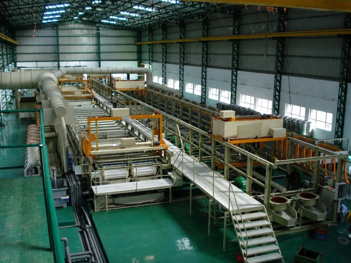
The operating weight of a plating line includes more than the empty tanks and steel structure. It includes process solution, anodes, racks, workpieces, piping, platforms, auxiliary equipment, and moving transfer loads. A qualified structural engineer should review the final loads and support points for the actual building.
Floor level and drainage slope must be coordinated. Tank supports require stable bearing surfaces, while surrounding areas may need chemical-resistant protection and controlled drainage. Trenches, pits, embedded pipes, and anchors should be positioned from the approved equipment drawing. Moving a floor drain after the line has arrived is far more disruptive than correcting it during the drawing review.
Vertical clearance is just as important as floor area. Check the highest hoist position, loaded rack height, lifting beam, installation crane or forklift mast, exhaust ducts, lighting, sprinklers, and roof structure. Door width, turning radius, loading-bay capacity, and the route from the truck to the final position should be checked against the largest shipping module, not the smallest machine component.
8. Leave Space for Operation and Maintenance
The equipment footprint is not the service envelope. Operators need safe loading and unloading positions, while maintenance teams need access to pumps, valves, sensors, heaters, chains, motors, tank internals, rectifiers, and plating filters. Chemical replenishment and sample collection also require practical routes that do not conflict with normal material movement.
During layout review, ask how each major component will be removed if it fails. A pump may be visible but still impossible to lift because a duct passes above it. A heater flange may face a wall with no withdrawal clearance. A compact layout can save floor space, but reducing the maintenance envelope often transfers that saving into future downtime.
9. Define the Responsibility Boundary
Site delays often occur because both parties assume the other party is supplying the same item. Responsibility varies by contract, so every interface should have a named owner, an agreed connection point, and a completion date.
| Typical item | Responsibility to define in the contract |
|---|---|
| Main power and local machine wiring | Who brings power to the line, who supplies isolators, and where the supplier's wiring begins |
| Water, air, heating, and cooling | Required conditions at the connection point and who supplies each upstream utility |
| Exhaust and gas treatment | Who supplies hoods, branch ducts, main ducts, fans, scrubber, stack, and building penetrations |
| Drainage and wastewater | Who provides the line discharge data, collection pipework, treatment plant, monitoring, and permits |
| Foundation, unloading, and rigging | Who approves the floor, prepares anchors, receives the shipment, and positions each module |
| Installation and commissioning | Supplier supervision, local labor, tools, test media, chemicals, trial parts, and operator availability |
A simple responsibility matrix is usually more useful than a general sentence stating that the customer will “prepare the site.” It gives the project team something specific to check before shipment.
10. Documents to Complete Before Shipment
At minimum, the project team should review the latest approved versions of the following documents:
- General arrangement drawing with operating and maintenance clearances
- Foundation, support-point, and equipment-load drawing
- Utility schedule with capacities, conditions, and connection locations
- Electrical single-line information and control-panel list
- Piping and drainage interface drawing
- Exhaust hood, duct, fan, scrubber, and stack interface drawing
- Wastewater-stream and treatment-interface plan
- Unloading, storage, lifting, and rigging plan
- Site-readiness checklist with responsible persons and target dates
- Open-item list from design reviews and factory testing
The Factory Acceptance Test for an electroplating line verifies equipment before delivery, but it does not replace site inspection. The FAT punch list and the site-readiness list should be reviewed together before the shipping release.
11. Final Site-Readiness Check Before Equipment Arrival
Before the truck is dispatched, confirm the following points at the factory:
- The approved equipment layout matches the actual workshop dimensions.
- The floor, foundations, trenches, anchors, and protective coating are complete and ready for loading.
- Power, water, air, heating, cooling, drainage, and exhaust connections are in the agreed locations.
- Utilities are labeled, isolated, tested, and available at the required conditions.
- The wastewater system is ready before water trials or chemical commissioning begin.
- The unloading route, door openings, turning space, crane or forklift, and temporary storage area are confirmed.
- Service access has not been blocked by late building work, ducts, pipes, or other machines.
- Local permits, safety procedures, contractors, tools, trial parts, and responsible staff are available.
- All drawing revisions and open technical questions have an agreed status.
Conclusion
The right site-preparation question is not only, “Will the electroplating line fit in the workshop?” It is, “Can the line be unloaded, installed, connected, commissioned, operated, maintained, and later modified without avoidable rework?”
That answer depends on verified process data, a complete utility schedule, coordinated building interfaces, and clear responsibility between the equipment supplier and customer. Closing these points before shipment reduces installation delays and gives the commissioning team a much better starting position.
If you are planning a new rack or barrel plating project, contact Autoplatingtec with your part drawings, coating process, target production, workshop layout, incoming utility information, and local environmental requirements. Our engineering team can review the equipment and site interfaces as one complete project.
Frequently Asked Questions
What utilities are normally required for an automatic electroplating line?
Typical utilities include electrical power, process and rinse water, drainage, exhaust, heating or cooling, and compressed air where required. Wastewater treatment, chemical storage, data connections, and fire or safety systems may also interface with the line. The final list depends on the process chemistry and equipment scope.
How much power and water does an electroplating line need?
There is no universal value. Demand depends on tank volume, rectifier capacity, heated and cooled stages, pumps, filtration, dryers, rinse design, production schedule, and auxiliary environmental equipment. Use a project-specific utility schedule rather than a figure from another line.
When should site preparation begin?
It should begin during line design, before the general arrangement and utility interfaces are frozen. Civil and building-service work should be coordinated from approved drawings and checked again before the equipment is released for shipment.
Can an existing factory utility system be reused?
Often it can, but only after its capacity, condition, water or air quality, connection locations, compatibility, and compliance with local requirements have been verified against the new line. An available pipe or cable does not by itself prove that the service is suitable.
Who is responsible for preparing the electroplating workshop?
The customer commonly prepares the building and upstream utilities, while the equipment supplier provides equipment loads and connection requirements. The actual scope varies by contract, so the responsibility boundary, connection point, testing method, and completion date should be recorded for every interface.