English
 Español
Electroplating Rinse System Design Guide: How to Reduce Drag-Out and Water Consumption
In many electroplating line projects, rinse systems are often discussed after the main plating process, tank layout, and automation requirements have already been decided. However, rinse design has a direct impact on coating quality, chemical consumption, wastewater load, and long-term operating costs.
During automatic electroplating line design, Autoplatingtec evaluates the rinse system together with the plating process, part loading method, production capacity, and wastewater treatment requirements rather than treating it as an independent section. Six months into production the shop is fighting bath contamination, water spotting, and a wastewater bill nobody forecast.
Electroplating rinse system design deserves better treatment than that, because the rinse system quietly sets three things: how clean each downstream bath stays, how much effluent leaves the building, and a real share of the operating cost. It is also the hardest part of the line to fix afterward, since adding a rinse stage means finding floor space that was allocated three years earlier.
What makes rinsing easy to underestimate is that it looks like nothing is happening. A plating tank has visible engineering in it. A rinse tank looks like a box of water. Yet the rinse system carries the entire burden of removing the solution film that every workpiece drags out of every process tank, and that film governs almost everything downstream of it.
1. Drag-out is the design input, not the rinse tank
Drag-out is the solution carried out on the workpiece, the rack, and the barrel every time a load leaves a tank. Part geometry drives it. So do surface area, orientation on the fixture, solution temperature and viscosity, and how the hoist withdraws and holds the load.
Nearly every downstream number scales from that one quantity: the rinse water flow required, the rate at which nickel finds its way into the chrome bath, the metal load arriving at wastewater treatment. Size the rinse tanks first and you have inverted the dependency. The line then cannot be tuned during commissioning, because the quantity everything else depends on was never established.
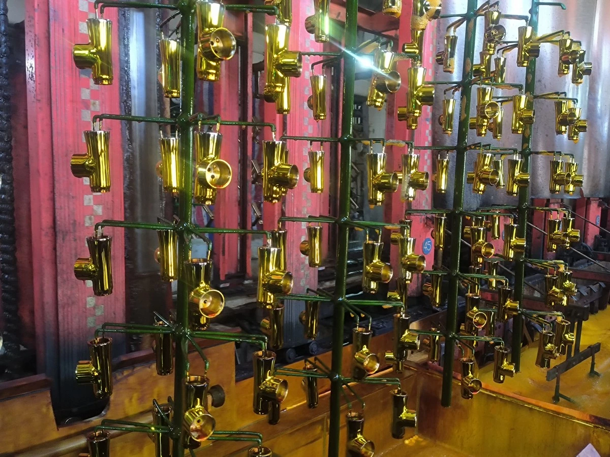
Two levers cut drag-out before a single rinse tank is involved. Fixture design is the first: parts hung so solution runs off, rather than sitting in cups, blind holes, and channels, leave far less liquid on the rack. This is one of the reasons rack design decisions influence yield and coating quality well beyond current distribution. The second lever is drain time above the tank. Longer drain means less drag-out and a longer cycle, so the two have to be settled together.
2. Estimating drag-out before sizing anything
You can estimate drag-out from part surface area and an assumed film thickness. The assumption is where projects go wrong. Film thickness shifts with solution temperature and concentration, with how the part hangs, and with whether the surface is polished or rough.
For a new line, bracket the estimate rather than averaging it. Calculate for the highest-surface-area part in the expected product mix and size to that. Lines specified around average loading fall over on the awkward jobs, and the awkward jobs are usually where the margin is.
Where a customer can send sample parts, the empirical route beats any table. Weighing a loaded fixture wet, then again after draining, is crude, but it produces a number that belongs to the actual job.
For new electroplating line projects, Autoplatingtec usually reviews part drawings, production requirements, coating specifications, and sample parts before proposing the rinse system design. This helps determine the suitable rinse stages, water consumption, and equipment layout based on the actual application.
For buyers planning the complete process, our automatic zinc and zinc-nickel plating line guide explains how coating requirements, loading, rinsing, post-treatment, controls, and RFQ data fit together.
3. Counterflow Cascade Rinsing: The Most Common Solution for Automatic Electroplating Lines
Dilution improves geometrically with the number of counterflow stages and only linearly with water flow. That single relationship explains most of what follows. In a counterflow cascade, fresh water enters the final rinse and overflows backward toward the first, so parts meet progressively cleaner water while the water meets progressively dirtier parts.
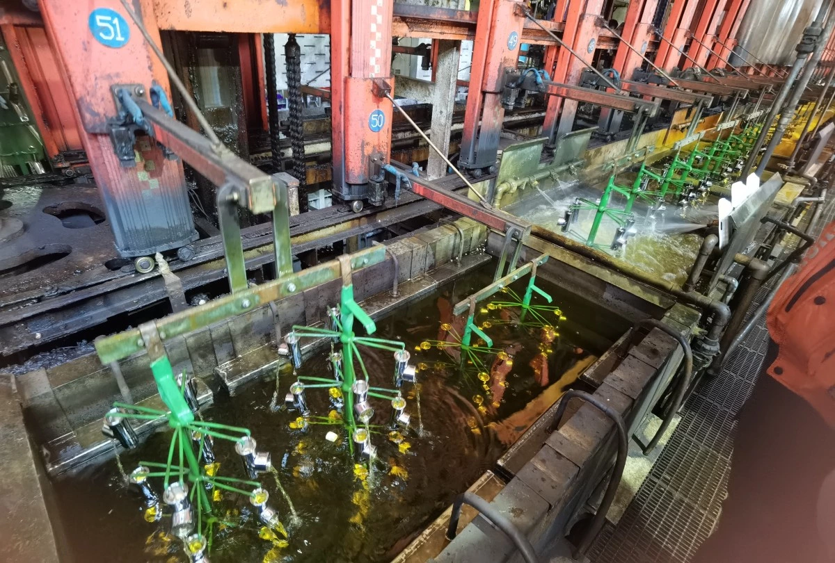
The practical consequence: adding a stage buys far more cleanliness per liter than opening the valve wider on an existing stage. A single running rinse can consume an order of magnitude more water than a two- or three-stage counterflow group reaching the same final dilution. How much more depends on the dilution ratio required and the drag-out volume, and it should be calculated for the specific process rather than borrowed from a similar line.
In automatic rack electroplating lines, counterflow rinsing is widely used because it provides better cleaning performance while reducing fresh water consumption. The number of rinse stages is normally determined by the drag-out volume, coating requirements, available space, and wastewater treatment capacity.
Stage count runs into three walls: floor space, cycle time, and capital cost. Each rinse position takes a station in the sequence and adds travel and handling to the hoist. On a rack electroplating line with a fixed footprint, an extra rinse stage costs either a process station or additional line length. Trading water and effluent cost against floor area belongs in the layout review, not in a change order after the steel is cut.
4. Matching the rinse method to part geometry and carrier type
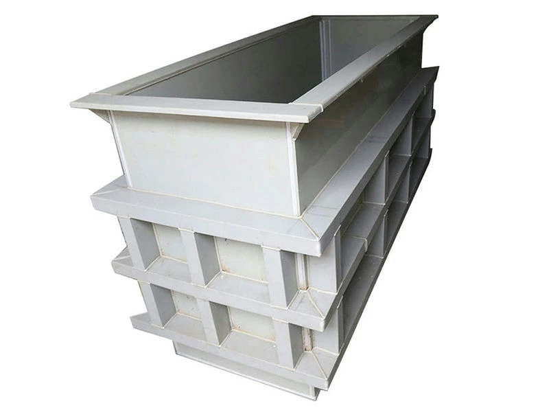
Immersion rinsing with air agitation handles most rack work, provided the drain and dwell behavior is right. Agitation matters more than soak time here: turbulence strips the film off the surface, whereas a still tank relies on diffusion and rinses badly.
Spray rinsing suits open, accessible geometry, and it uses water once at the point of contact instead of diluting a whole tank. A spray arrangement mounted over a process station returns rinse water straight to the bath and offsets evaporation. Parts with recesses, threads, or blind features defeat it, because the spray never reaches the solution held inside them.
Barrels behave differently again. Solution sits in the barrel body, in the perforations, and in the packed mass of parts, which adds up to considerably more than the film on an equivalent rack. Rinse stations on a barrel electroplating line usually need longer immersion with rotation, plus rotation above the tank while draining, to shake solution out from between parts. Specifying barrel rinses on rack-line assumptions is a familiar cause of disappointing results.
5. Dead rinse and drag-out recovery
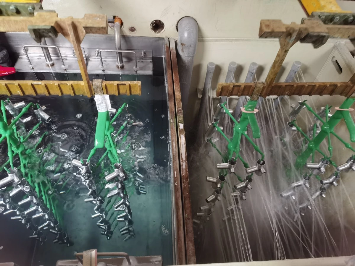
A dead rinse is a still tank, no overflow, sitting immediately after a process tank. It collects dragged-out chemistry instead of sending it down the drain, and its contents can go back into the bath it follows as make-up, particularly where that bath runs hot and loses volume to evaporation.
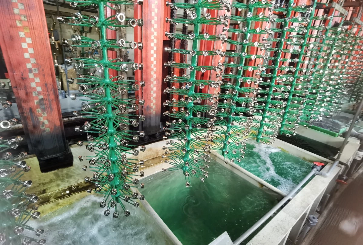
Recovery only works under two conditions. The process has to tolerate whatever contaminants come back with the recovered solution, and the evaporation rate has to leave enough volume headroom to accept it. Hot baths with high evaporation are the obvious candidates; cold baths frequently are not. Where the conditions hold, recovery cuts chemical purchasing and treatment load at the same time, which makes it worth evaluating at design stage rather than after the first year's water bill.
One caveat: a dead rinse concentrates over time and eventually stops rinsing anything. It buys drag-out reduction, not cleanliness, and an active rinse group always has to follow it.
6. Rinse water quality and the last-rinse problem
Incoming water quality puts a ceiling on how clean a part can get. Chlorides, sulfates, hardness, and dissolved solids do not vanish during rinsing. They stay on the part when the final rinse dries. Water spotting, staining, and adhesion failures blamed on the plating bath often trace back to the rinse water instead.
Deionized or reverse-osmosis water in the final rinse is normal practice for decorative finishes and for parts that get coated afterward. Treating every stage is usually wasteful; feeding treated water to the last stage and cascading its overflow backward serves the earlier stages perfectly well. Whether treatment is needed at all, and to what specification, comes from a water analysis of the actual supply rather than from regional assumptions.
7. Where rinses sit in the sequence, and what they cost in cycle time
A rinse station occupies the hoist exactly as a process station does. Move, lower, dwell, raise, drain, move on. That time enters the cycle calculation, and a rinse group that is chemically correct but missing from the timing model will either push the cycle past the output target or get shortened by operators under pressure, which defeats the design without anyone recording that it happened.
Sequence also decides contamination paths. An acid rinse discharging into a common alkaline drain, or a chrome rinse sharing a line with cyanide-bearing effluent, produces treatment problems that cost real money later and cost nothing to avoid on the layout drawing. Segregating rinse discharge by chemistry is a decision made on paper.
8. Common Rinse System Design Mistakes in Electroplating Projects
Based on experience from electroplating line projects, several rinse system problems are caused by decisions made too late during the design stage.
- Insufficient rinse stages
Some projects reduce rinse tanks to save initial investment, but this may increase chemical contamination between processes and create unstable coating quality.
- No consideration of future production changes
A rinse system designed only for current products may become insufficient when part sizes, production volume, or coating requirements change.
- Separate design of plating and wastewater systems
The rinse system, chemical recovery, and wastewater treatment should be considered together during the layout stage. Otherwise, additional piping and modifications may be required after installation.
9. Instrumentation and control
Older installations run manual valves and continuous overflow, and that combination wastes more water than anything else on a typical line. The water runs whether parts are in the tank or not.
Conductivity-controlled make-up switches the logic around: fresh water enters only when contamination crosses a set point. Flow-restricting orifices and solenoid valves interlocked with hoist position achieve much the same thing with simpler hardware. Either way, the set point has to be established during commissioning against real parts, since the relationship between conductivity and residual contamination belongs to the specific process.
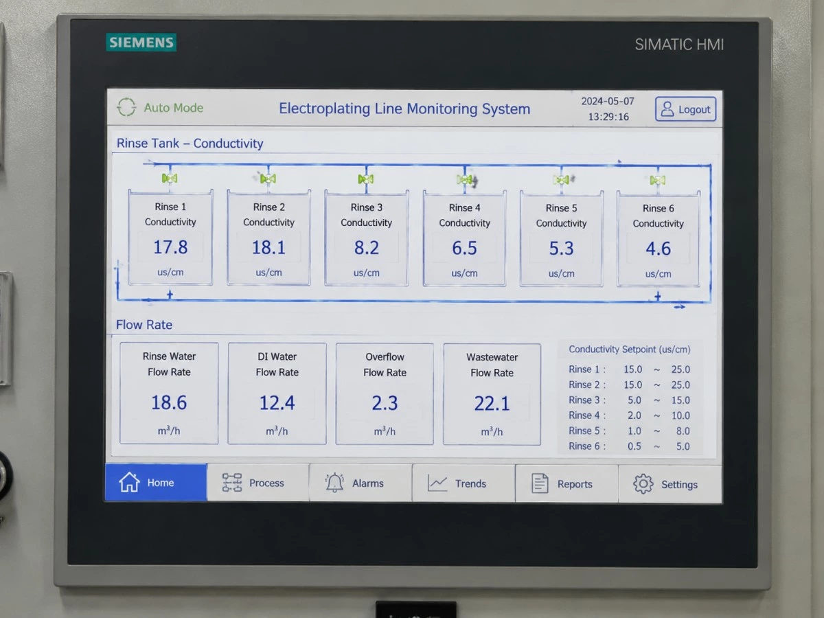
Noted: Modern automatic electroplating lines can monitor rinse conductivity and water flow through an HMI control system, helping operators maintain stable rinsing performance and reduce unnecessary water consumption.
Compared with the water and effluent it saves across a line's service life, rinse instrumentation is cheap. It is also far easier to build in than to retrofit into a running line.
10. Interfaces with exhaust and effluent treatment
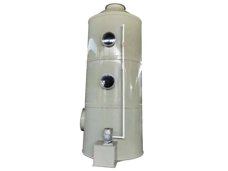
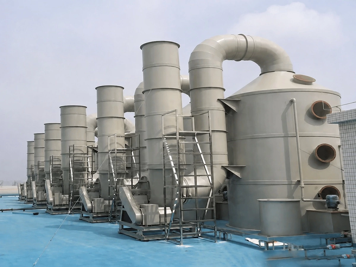
Rinse tanks following hot or fuming baths carry vapor and mist of their own, and often need extraction rather than borrowing the neighboring process hood. Extraction volumes and hood arrangements for rinse positions should enter the exhaust gas treatment system scope at the start. Adding hoods after ductwork is fabricated disrupts the installation and tends to unbalance the whole extraction system.
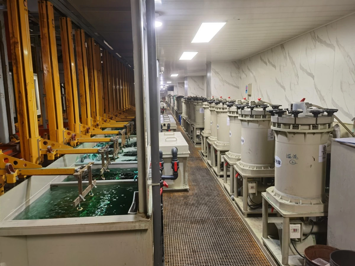
Noted: The rinse system directly affects wastewater treatment requirements because it determines both water volume and metal concentration entering the treatment system.
On the effluent side, the rinse system defines both the hydraulic and the metal load reaching wastewater treatment. Halving rinse flow halves the hydraulic load and concentrates the same metal into a smaller volume, which is generally cheaper to treat. Discharge limits, monitoring obligations, and permitted flow are subject to applicable local requirements, and they need confirming for the specific site before anyone sizes a treatment plant.
Conclusion
The chain runs one way. Part geometry and fixture design set drag-out; drag-out sets the dilution ratio and therefore the stage count; stage count consumes floor space and hoist time, which decides whether the line hits its output target; rinse flow sizes the wastewater plant; rinse water quality decides whether the finish is acceptable. Reversing that order is what produces problem lines.
None of these variables can be optimized alone. Squeeze water consumption hard enough and the cycle stretches past the throughput target. Squeeze cycle time instead and contaminated solution travels into downstream baths, raising chemical consumption to pay for the time saved. Where the balance point sits depends on local water cost, local discharge limits, available floor area, and the real product mix, which is why rinsing has to be worked out during layout alongside the process sequence and the transfer system. The same logic governs planning an automatic rack electroplating line as a whole.
As an electroplating line manufacturer, Autoplatingtec considers rinsing, process tanks, automation control, exhaust systems, and wastewater treatment interfaces as one complete production system during line planning.
Frequently Asked Questions
1. How many rinse stages does an electroplating line need?
It depends on the dilution ratio the process requires and the drag-out volume per load, so there is no universal number. The calculation runs from drag-out, not from the tank count. Since dilution improves geometrically with each counterflow stage, most lines reach the required cleanliness with fewer stages than a single-stage running rinse would need in water volume.
2. What is drag-out in electroplating?
Drag-out is the process solution carried out of a tank on the workpiece, the rack, or the barrel when a load is lifted. It determines rinse water demand, the rate at which downstream baths become contaminated, and the metal load reaching wastewater treatment. Reducing it through fixture design and drain time is cheaper than rinsing it away.
3. How much water does a plating line use?
Water consumption is a result of the rinse design rather than a property of the line. The governing factors are drag-out volume per load, the number of counterflow stages, whether rinse flow is continuous or demand-controlled, and how many loads run per shift. Two lines producing identical parts can differ substantially on all four.
4. Can rinse water be reused in electroplating?
Yes, under specific conditions. A dead rinse placed immediately after a hot process tank collects dragged-out chemistry that can return to the bath as make-up, provided the bath tolerates the returning contaminants and evaporation leaves volume headroom to accept it. Cold baths with low evaporation usually cannot absorb recovered solution.
5. Does every rinse tank need deionized water?
Generally no. Treated water in the final rinse, cascading backward to feed earlier stages, meets most requirements at a fraction of the cost of treating every stage. Whether DI or RO water is needed at all depends on the incoming supply analysis and the finish specification, particularly for decorative finishes and parts that receive a subsequent coating.
6. What causes water spots on plated parts?
Dissolved solids in the rinse water are a frequent cause. Chlorides, sulfates, and hardness left on the surface stay behind when the final rinse dries, producing spots and stains that are often misattributed to the plating bath. Inadequate final-rinse cleanliness and insufficient drying capacity are the other common contributors.
7. How do manufacturers design a rinse system for a new electroplating line?
The design normally starts with part information, coating requirements, production capacity, drag-out estimation, and water quality requirements. Based on these factors, the engineering team determines rinse stages, water flow, tank arrangement, and control methods. For automatic electroplating lines, rinse design should be completed together with the overall line layout.
Discuss your line with the engineering team
Engineers specifying a new line or auditing an existing one are welcome to send Autoplatingtec the inputs needed to work the problem properly: part drawings or sample parts, the substrate and coating specification, target output per hour or per shift, available floor area and ceiling height, an incoming water analysis, local discharge limits, and any site constraint on effluent volume. With those in hand, rinse stage count, rinse method, water quality requirement, and treatment interfaces can be proposed as part of the line layout instead of being added to it later. Contact details are on the contact page.