English
 Español
Automatic Zinc and Zinc-Nickel Electroplating Line: What Buyers Should Specify
An RFQ that says only “automatic zinc plating line for automotive parts” is not yet a line specification. It identifies the coating family, but it does not tell an equipment supplier how the parts will be loaded, how many loads must move through the plant, which post-treatment is required, or whether the finished parts are subject to a customer-specific corrosion and traceability standard.
That missing information has a direct cost. One supplier may assume a rack line with several parallel plating stations. Another may assume barrel processing, a different pretreatment sequence, or a separate hydrogen-embrittlement relief oven. Their quotations can look impossible to compare because they are not pricing the same production system.
A reliable automatic zinc electroplating line starts with the coating requirement and the real production mix, not with a standard tank list. The same applies to a zinc-nickel plating line. The equipment, controls, rinsing, post-treatment, exhaust, and wastewater interfaces all have to support the approved process as one system.
This guide explains the information a buyer should define before asking for a layout and quotation. It is written for new lines and major line upgrades using rack, barrel, or combined production.
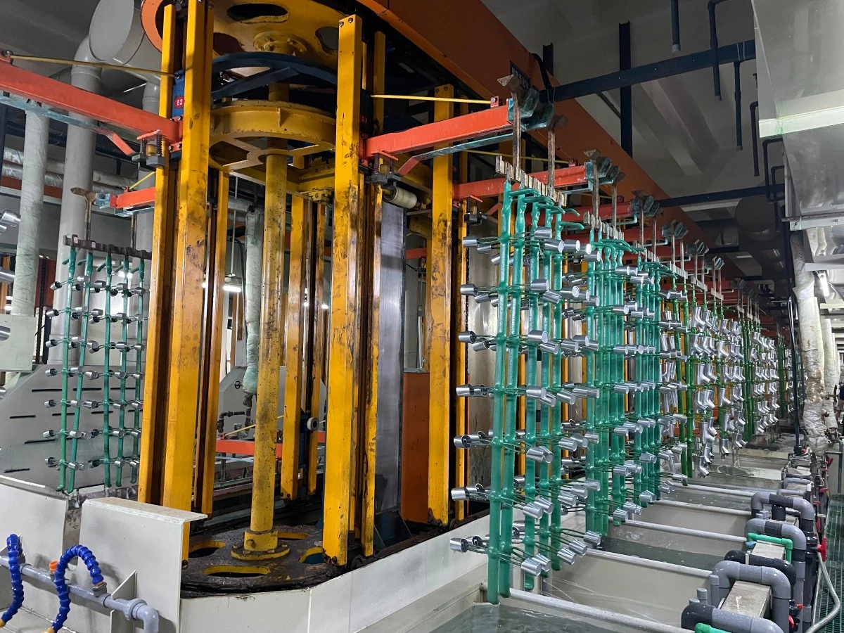
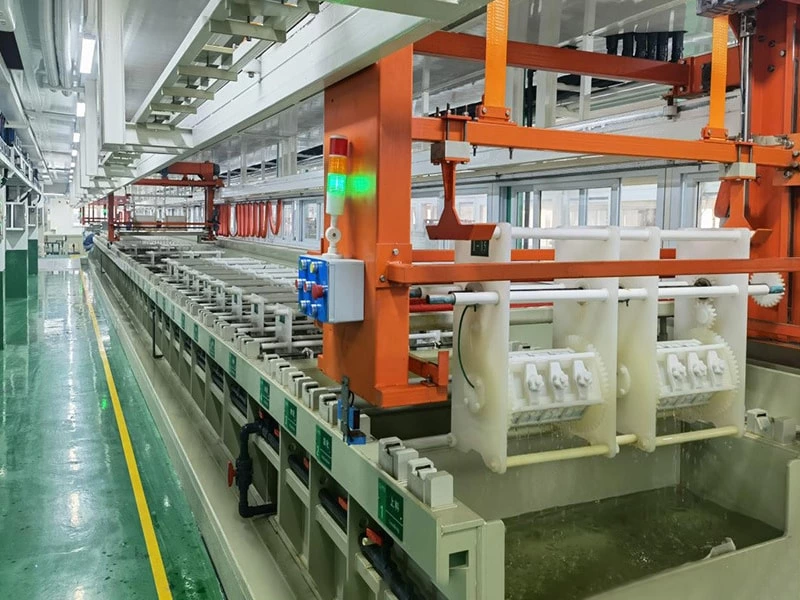
Metal parts moving through an automatic rack electroplating line. The final process sequence and operating parameters are configured according to the part family and coating specification.
1. Begin with the Coating Specification
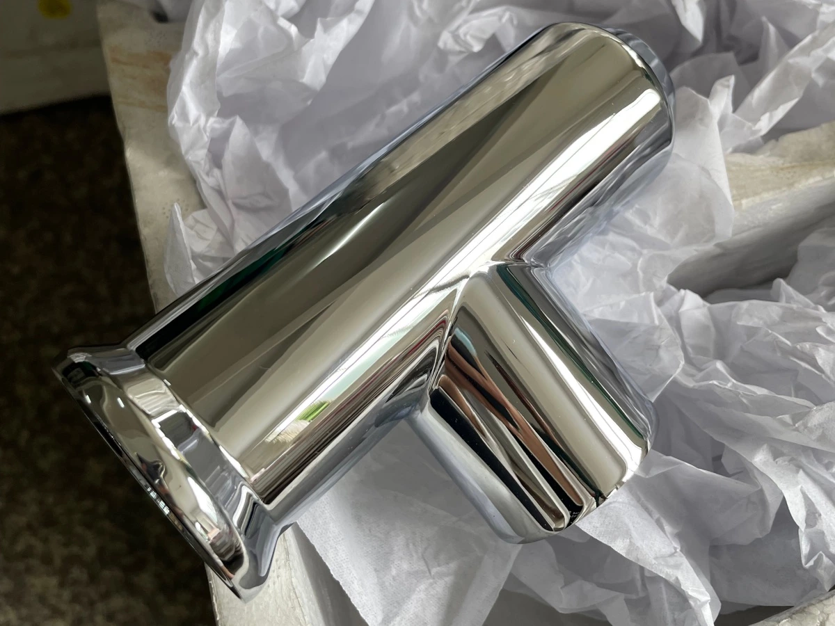
“Zinc” and “zinc-nickel” are not complete coating specifications. Before equipment design starts, the buyer should identify the substrate, coating system, thickness requirement, supplementary finish, appearance, corrosion test, and any customer or industry standard that applies.
Examples of reference standards include ASTM B633 for electrodeposited zinc on iron and steel, ASTM B841 for zinc-nickel alloy deposits, ISO 19598 for zinc and zinc-alloy coatings with Cr(VI)-free supplementary treatment, and ISO 4042 for electroplated fasteners. The project must use the exact standard, revision, drawing note, or customer specification required for the finished part. A general reference to “automotive quality” is not enough.
The required post-treatment also changes the line. Clear and black passivation, sealers, topcoats, lubricants, and friction-control finishes are not interchangeable steps. Their tank arrangement, rinsing, drying, handling, and quality checks should be agreed before the equipment scope is frozen.
- State whether the coating is plain zinc, zinc-nickel, or whether both must be produced.
- Provide the specified coating thickness and the permitted variation.
- Identify the passivation color and whether a sealer, topcoat, or lubricant is required.
- Provide the corrosion-test method and acceptance criteria from the governing specification.
- Identify appearance limits, contact-mark restrictions, dimensional limits, and thread requirements.
- Confirm whether high-strength steel or safety-critical parts require special embrittlement controls and batch traceability.
A line intended to produce both zinc and zinc-nickel needs a defined equipment and production strategy. Sharing a structural frame or utility system is not the same as sharing process tanks. Bath chemistry, anode arrangement, post-treatment, contamination control, and production scheduling must be reviewed separately.
2. Build a Real Part and Production Model
Production capacity cannot be calculated reliably from annual tonnage alone. A tonne of small fasteners behaves differently from a tonne of large brackets. The number of pieces per rack or the mass per barrel, part surface area, process time, transfer time, drain time, changeover pattern, and available production hours all affect line output.
Create a part-family table rather than designing around one convenient sample. Include the smallest and largest parts, the highest-surface-area load, the heaviest load, the most difficult geometry, and any part that has a separate coating or post-treatment requirement.
For each family, provide:
- Part drawing, photograph, base material, heat-treatment condition, and hardness or strength information where relevant
- Overall dimensions, unit mass, estimated surface area, and monthly or daily quantity
- Blind holes, tubes, folded sections, deep recesses, threads, sharp edges, and areas that trap solution
- Incoming oil, rust, scale, heat-treatment residue, or other surface condition
- Permitted contact locations, cosmetic surfaces, masking needs, and acceptable handling marks
- Required lot separation, color change, recipe change, and traceability level
Sample parts are particularly useful. Loading trials can reveal tangling, nesting, air pockets, poor drainage, weak rack contacts, and impact damage that are not obvious from a drawing. When samples are unavailable, clear 3D models and photographs should accompany the drawings.
For a step-by-step method that converts part demand into load intervals, parallel process positions and supporting-equipment requirements, see our electroplating line capacity calculation guide.
3. Rack, Barrel, or Both?
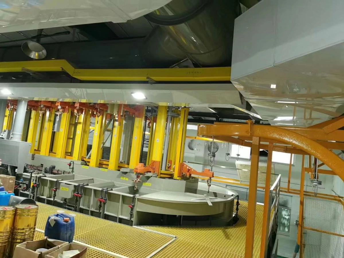
The loading method is one of the first equipment decisions. A rack electroplating line holds parts individually and gives the designer control over orientation, electrical contact, drainage, and separation. A barrel electroplating line processes many small parts as a bulk load while the barrel rotates.
| Design question | Rack processing | Barrel processing |
|---|---|---|
| Typical part condition | Larger, fragile, appearance-sensitive, complex, or individually oriented parts | Small, robust parts that can tolerate bulk contact and controlled tumbling |
| Electrical contact | Defined rack contacts at selected locations | Contact through the barrel load and approved current-delivery arrangement |
| Handling risk | Contact marks, incorrect orientation, or weak fixture retention | Tangling, nesting, thread damage, impact marks, or parts lodging in perforations |
| Capacity basis | Parts and total surface area per rack | Part mass, fill level, surface area, and movement within each barrel |
| Drain and rinse behavior | Driven by part orientation, rack geometry, withdrawal, and drain time | Driven by retained solution in the barrel and the packed part load, plus rotation and drain time |
Barrel plating is not automatically the right answer for every small part. Long parts can tangle, thin stampings can nest, delicate edges can be damaged, and threaded components may require validated barrel loading and handling. Rack plating is not automatically better either; manual loading can become a labor bottleneck, and poor contact design can reduce usable rack capacity.
If the factory needs both methods, the project should define whether rack and barrel sections are independent, whether selected pretreatment or post-treatment stages are shared, and how simultaneous production will affect hoist traffic, chemistry control, and wastewater load.
4. Build the Process Sequence Around the Actual Parts
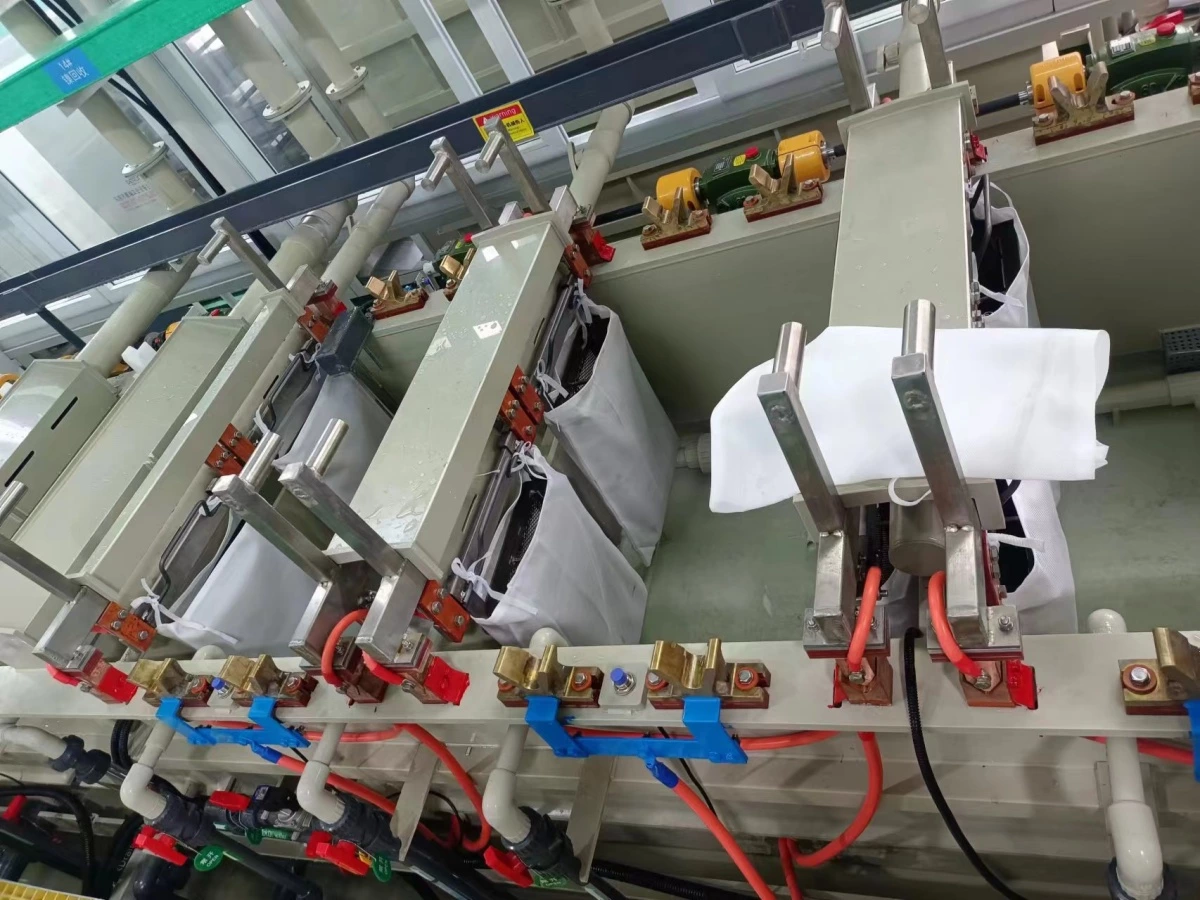
A typical steel-part line may include cleaning, electrocleaning where required, rinsing, acid activation or pickling, further rinsing, zinc or zinc-nickel deposition, recovery and rinsing, preparation for passivation, passivation, supplementary treatment, and drying. This is only a process framework. The exact chemistry, stage count, sequence, operating conditions, and control limits must be approved for the substrate and coating specification.
Pretreatment deserves the same attention as the plating tank. An aggressive route chosen for scaled components may be unsuitable for a cleaner or higher-strength part family. Conversely, a short cleaning sequence may fail when incoming parts carry forming lubricant, polishing compound, heat-treatment scale, or corrosion inhibitor.
For every stage, the equipment designer needs:
- Required immersion and processing time
- Operating temperature and acceptable control range
- Agitation, circulation, filtration, heating, or cooling requirement
- Tank material and chemical compatibility
- Workpiece movement, barrel rotation, rocking, or other mechanical action
- Drain time and any requirement to return drag-out to the process tank
- Sampling, dosing, analysis, and maintenance access
Do not treat the process sequence as a drawing that can be finalized after the transfer system is ordered. Dwell times, drain positions, parallel stations, hoist routes, and control recipes are what determine the transfer-system requirement.
5. Size Tanks and Transfer Equipment as One System
A tank can be large enough for the workpiece and still be too small for stable production. The design also needs clearance for racks or barrels, anodes and baskets where used, agitation, heating or cooling devices, circulation, filtration returns, exhaust hoods, level variation, and safe maintenance access.
Capacity calculations should start from the approved loading plan and cycle model. If the plating dwell is longer than other stages, the line may require parallel plating positions. If passivation colors change frequently, separate stations or a deliberate cleaning and changeover method may be necessary. If drain time is shortened merely to achieve the target cycle, chemical drag-out and rinse loading may rise.
The hoist or transfer system must be checked for more than lifting capacity. Review loaded rack or barrel weight, acceleration, positioning accuracy, sway control, vertical clearance, drip management, collision zones, maintenance access, manual recovery, and the route used after a fault or power interruption.
For a detailed look at rack-line timing, loading, and transfer interactions, see our automatic rack electroplating line planning guide.
6. Match Rectifiers and Current Delivery to the Load
Rectifier capacity should be calculated from the maximum plated surface area per load and the approved current-density operating window, with the process supplier's input. Part mass alone does not provide that information. Two loads with the same weight can have very different surface areas and current demand.
The current path also changes with the loading method. Rack contacts, busbars, hooks, cathode movement, barrel contacts, cables, and barrel rotation all contribute to voltage loss and current distribution. Their condition must remain inspectable and maintainable after the line enters production.
For automatic production, the control system should coordinate rectifier output with the correct load, bath, recipe, and process time. Useful functions can include programmed ramps, current or ampere-hour recording, out-of-range alarms, interlocks, and batch records. The exact functions should follow the customer's quality plan rather than being added as an unused list of software options.
7. Define Bath Support Equipment and Chemistry Interfaces
The plating tank cannot be designed in isolation from filtration, circulation, temperature control, anode strategy, replenishment, and analysis. Zinc and zinc-nickel baths may require different arrangements, and the approved chemistry supplier should confirm the operating and materials requirements before final equipment selection.
Important interfaces include:
- Pump, pipe, seal, filter, heat-exchanger, heater, and tank-material compatibility
- Filtration flow path and placement of suction and return connections
- Temperature measurement, heating or cooling capacity, and circulation during idle periods
- Anode type, baskets or other approved arrangement, and maintenance access
- Dosing locations, day tanks, transfer pumps, level controls, and chemical storage boundaries
- Sampling points and the relationship between laboratory analysis and automatic additions
Automatic dosing is not the same as automatic chemistry control. A pump can add a chemical accurately and still add the wrong amount if the input data or control rule is wrong. The project should define which additions are flow-based, ampere-hour-based, analysis-based, or manually authorized, and how operators verify the result.
Continuous solution cleanliness may also require correctly selected plating filters, but filtration media, flow, maintenance interval, and spare capacity should be chosen for the actual bath rather than copied from a different process.
8. Design Rinsing from Drag-Out, Not from Habit
Every load carries process solution into the next stage. The amount depends on part shape, orientation, surface area, rack or barrel design, solution properties, withdrawal method, and drain time. That drag-out determines rinse contamination, fresh-water demand, chemical loss, and a significant part of the wastewater load.
A rinse section may combine recovery rinses, counterflow stages, spray rinsing, controlled overflow, conductivity monitoring, or demand-based water addition. The right combination depends on the process and required final cleanliness. Adding water to compensate for poor drainage is usually an expensive substitute for fixing the loading and drain strategy.
Rack and barrel loads must be evaluated separately. A rotating barrel and packed mass of parts can retain solution in a way that a rack-load estimate does not represent. The stage time, rotation above the tank, transfer delay, and rinse movement need to be included in the cycle model.
Our electroplating rinse system design guide explains how drag-out, counterflow stages, water quality, and wastewater capacity connect to the production line.
9. Treat Passivation, Sealing, Drying, and Baking as Production Stages
Post-treatment is not a small finishing section added after the main line has been designed. Clear or black passivation, a sealer, topcoat, lubricant, and final rinse can determine both coating performance and appearance. Their control, contamination sensitivity, handling, and drying requirements need dedicated space and time.
Parts should not be damaged or contaminated between these stages. Rack angle, barrel unloading, transfer trays, centrifuges where applicable, dryers, and cooling or inspection areas should support the approved finish. For appearance-sensitive work, droplets trapped in recesses and uncontrolled drying can create marks even when the deposited coating is acceptable.
Hydrogen embrittlement risk requires a separate engineering review for applicable steel parts, particularly high-strength fasteners and safety-critical components. The governing drawing or coating standard should define any stress-relief or embrittlement-relief requirement, permitted delay, oven cycle, and relationship to supplementary finishes. There is no universal baking time and temperature that should be applied to every part.
If an oven is included, size it from the real batch mass, fixture or basket arrangement, heating and recovery cycle, and line output. The control system should prevent a batch from losing identity between plating and baking and should record the required process data.
10. Plan Exhaust and Wastewater with the Process Line
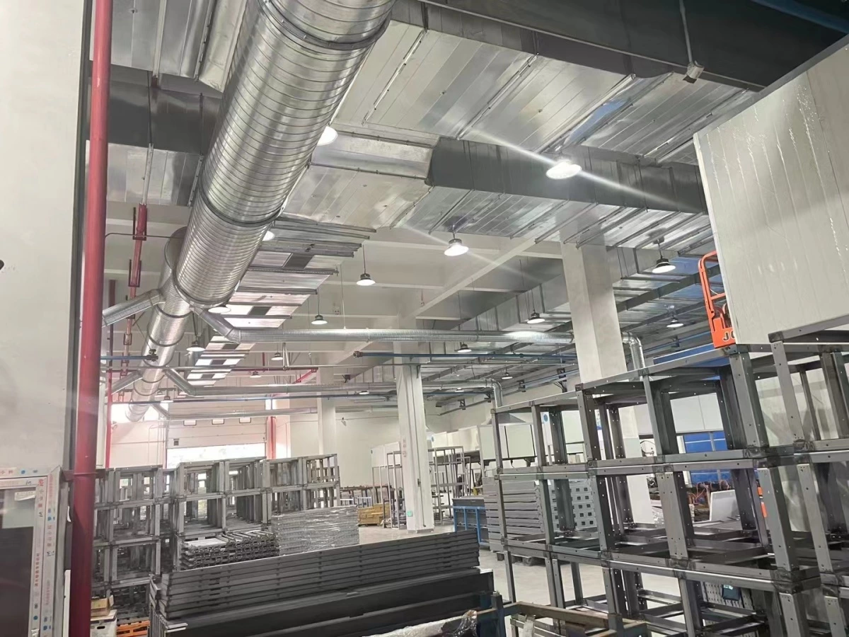
Exhaust design depends on the chemistry, bath temperature, agitation, tank area, loading movement, hood geometry, and local occupational and environmental requirements. Acid pretreatment, process baths, passivation, stripping or maintenance tanks, and drying equipment may have different collection needs. A single airflow copied from another project is not a safe design basis.
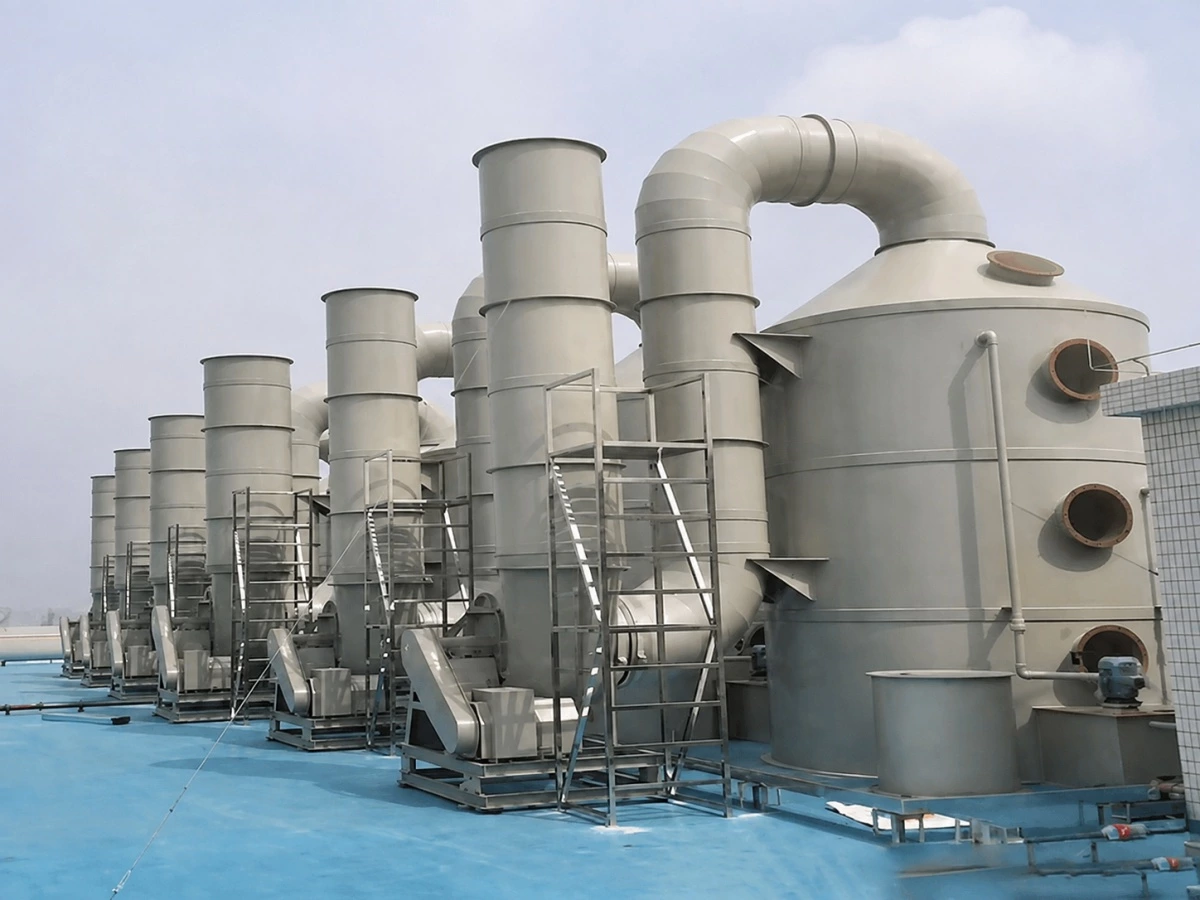
Tank hoods, branch ducts, main ducts, fan, scrubber, make-up air, stack, drainage, and controls should be reviewed as one system. The route must also clear the moving racks or barrels, hoists, platforms, lighting, roof structure, and maintenance paths. See our electroplating gas treatment systems for typical supporting equipment.
Wastewater planning begins with a stream list. Cleaner rinses, acid rinses, zinc-bearing rinses, zinc-nickel rinses, passivation stages, scrubber discharge, floor wash water, and concentrated maintenance solutions should not be connected together without a treatment review. Local engineers must decide which streams require segregation, batch collection, recovery, pretreatment, or monitoring.
The plating line supplier should provide expected stream sources and operating information. The customer's environmental team and local wastewater designer should confirm treatment capacity, discharge requirements, permits, storage, containment, and emergency response. A line quotation should state clearly which environmental equipment is included and where the supplier's responsibility ends.
11. Controls Should Protect the Process, Not Just Move the Hoist
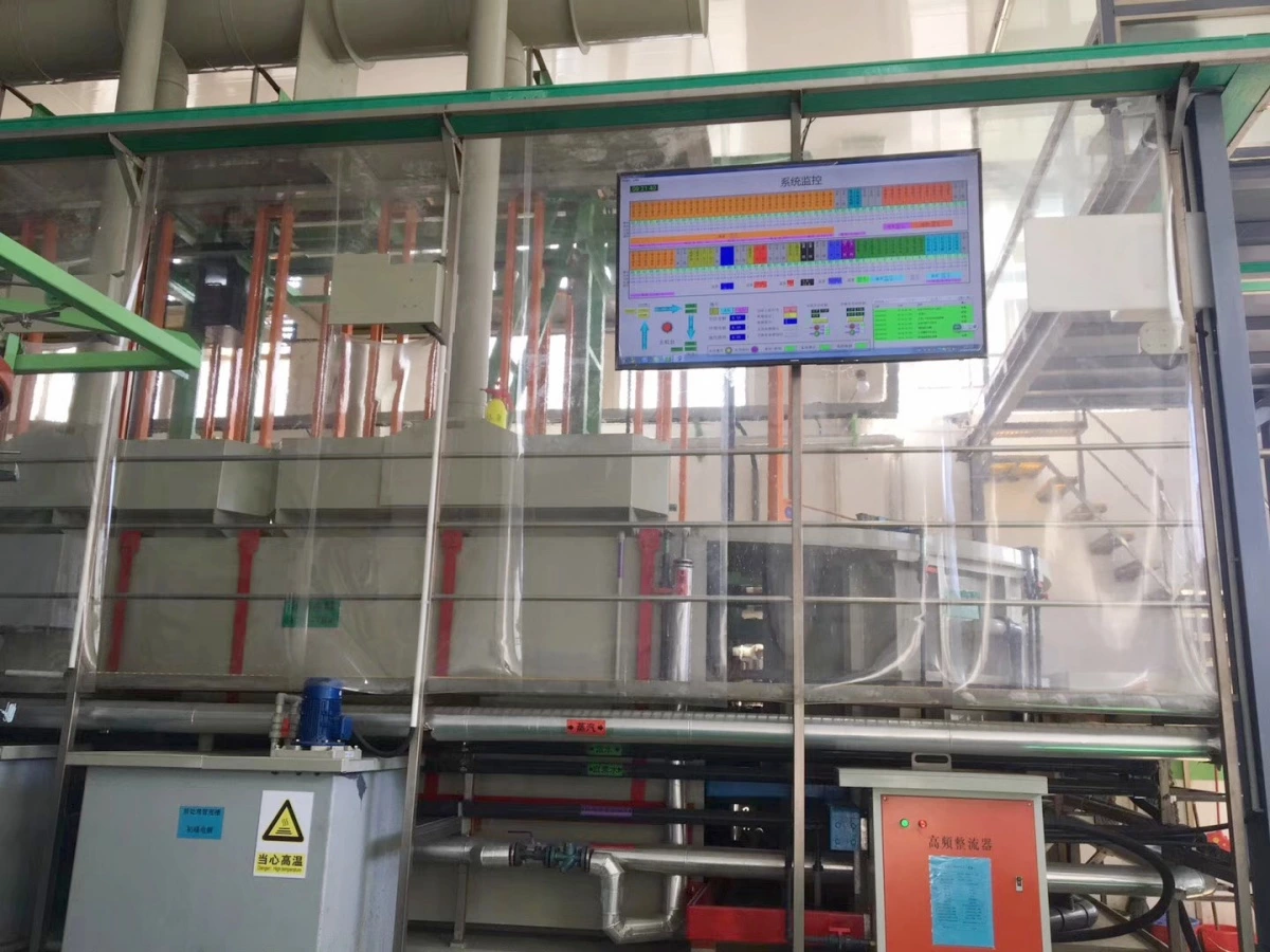
A PLC and touchscreen do not by themselves make a plating line reliable. The control philosophy should address normal automatic production, manual maintenance, recipe changes, abnormal recovery, and traceability.
Depending on the project, useful control functions may include:
- Recipe selection linked to the approved part family and coating system
- Rack, barrel, or batch identification and route control
- Immersion, drain, transfer, barrel-rotation, and process-time monitoring
- Rectifier, temperature, flow, level, filtration, and exhaust interlocks
- Alarm priorities with a defined operator response
- Collision prevention and safe recovery after a stopped move
- Production, alarm, maintenance, and quality records at the required retention level
- User permissions and controlled changes to recipes or process limits
Traceability should be specified rather than assumed. Some plants only need a production count and alarm history. Others need the bath, recipe, current record, time, operator, material lot, passivation route, and baking record connected to each batch. That difference affects sensors, identification hardware, software, database scope, and validation work.
12. Give Suppliers an RFQ They Can Engineer
A useful RFQ does not need to contain the final machine design. It needs enough verified input for suppliers to calculate and declare their assumptions. The following information should be provided before comparing technical proposals.
| RFQ section | Information to provide |
|---|---|
| Coating | Zinc or zinc-nickel, governing specification, thickness, passivation, sealer or topcoat, appearance, corrosion test, and inspection requirement |
| Parts | Drawings, photos, material, hardness or strength where relevant, dimensions, mass, surface area, geometry risks, threads, masking, and contact limits |
| Production | Quantity by part family, shifts, operating days, batch or lot size, product mix, changeovers, peak demand, and future capacity |
| Loading | Rack or barrel preference, existing fixtures, loading trials, sample parts, acceptable handling marks, and loading or unloading automation |
| Factory | Workshop dimensions, layout, floor and height limits, power, water analysis, heating, cooling, compressed air, drainage, exhaust route, and access |
| Environmental | Local ventilation and discharge requirements, wastewater plant capacity, stream-segregation plan, containment, monitoring, and required permits |
| Scope and acceptance | Required equipment boundary, documentation, FAT, installation, commissioning, trial parts, training, spares, warranty, and performance-acceptance method |
If some inputs are not yet available, identify them as open items instead of allowing every supplier to make a different hidden assumption. A good technical proposal should show the process basis, loading basis, calculated capacity, equipment scope, exclusions, utility schedule, responsibility boundary, and items that still require customer approval.
13. Compare Scope Before Comparing Price
Two automatic zinc plating line quotations can have similar tank counts and completely different scope. One may include rectifiers, filtration, platforms, exhaust hoods, main ducting, scrubber, RO water, a baking oven, installation supervision, and process commissioning. Another may stop at tanks, a frame, and a transfer system.
Before comparing price, place each proposal against the same scope list:
- Process tanks, rinse tanks, frames, platforms, guards, and access
- Rack, barrel, hoist, loading, unloading, and transfer equipment
- Rectifiers, busbars, contacts, control cabinets, HMI, software, and data functions
- Pumps, filters, pipework, valves, heating, cooling, dosing, and bath-support equipment
- Exhaust hoods, ducts, fan, scrubber, stack interface, and make-up-air assumptions
- Water treatment, wastewater interfaces, containment, and concentrated-waste handling
- Passivation, sealing, drying, baking, cooling, and finished-part handling
- Drawings, manuals, spare parts, FAT, packing, shipment, installation, commissioning, training, and acceptance testing
Factory Acceptance Testing should verify the agreed mechanical, electrical, control, safety, documentation, and dry-cycle functions before shipment. Our guide to FAT for electroplating lines explains what it can confirm and what must wait until site commissioning.
The customer's building and utility work also needs to follow the approved equipment interfaces. Use the electroplating line site-preparation checklist before the equipment is released for delivery.
Conclusion
An automatic zinc or zinc-nickel electroplating line cannot be selected responsibly from coating name and annual tonnage alone. The equipment design depends on the finished coating specification, real part families, rack or barrel loading, process times, current demand, rinsing, post-treatment, embrittlement controls, environmental interfaces, and required production records.
The best time to resolve these points is before suppliers finalize their layouts. A clear RFQ produces proposals that are easier to compare, exposes missing scope early, and gives the engineering team a defensible basis for capacity, utility, and acceptance decisions.
If you are planning a new automatic zinc or zinc-nickel plating project, contact Autoplatingtec with your part drawings, coating specification, production target, preferred loading method, workshop layout, and local utility and environmental requirements. Our engineering team can review the line configuration and supporting systems as one project.
Frequently Asked Questions
Can one automatic line produce both zinc and zinc-nickel coatings?
It may be possible within one project, but the design needs a defined strategy for dedicated process tanks, post-treatment, contamination control, anode and bath-support equipment, recipes, and production scheduling. The supplier should not assume that the same tank can switch freely between the two chemistries.
Should zinc-plated parts use rack or barrel processing?
Rack processing is commonly selected when parts need individual orientation, controlled contacts, separation, or protection from bulk impact. Barrel processing is commonly selected for small, robust parts that can move together without tangling, nesting, thread damage, or unacceptable marking. The decision should be verified from representative parts and the required output.
How many tanks does a zinc plating line need?
There is no universal tank count. It depends on incoming part condition, approved pretreatment, plating time, rinse quality, passivation and supplementary finishes, parallel capacity, maintenance strategy, and whether multiple part families or coating systems must run. The process sequence and cycle model should be approved before the tank count is fixed.
Is a hydrogen-embrittlement relief oven always required?
No. The requirement depends on the part material, hardness or tensile strength, manufacturing history, safety function, and governing coating or customer specification. Where relief is required, the permitted delay, cycle, batch handling, traceability, and relationship to supplementary finishes must be defined for that part.
Can a supplier calculate line capacity from kilograms per day?
Weight is only one input. Reliable capacity calculations also require part surface area, pieces per rack or mass per barrel, loading and unloading time, dwell time at every stage, drain and transfer time, changeovers, shift pattern, equipment availability, and the product mix. Capacity should be shown by representative part family, not only as one daily tonnage.
What information is needed for an initial zinc plating line quotation?
Provide part drawings and photos, base material, size, mass, estimated surface area, coating specification, passivation or topcoat, daily or monthly volume, shift schedule, rack or barrel preference, workshop layout, available utilities, environmental requirements, and the expected supply and service scope. Sample parts make the initial loading and handling review more reliable.